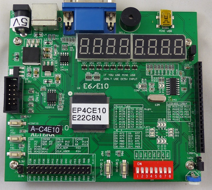
Features
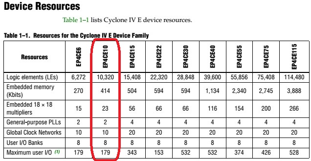
- 46 Internal SRAM 1KX9 Blocks
Interface
24C04 I2C EEPROM
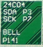
Buzzer

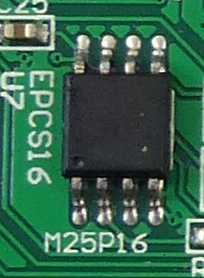
EPCS
Connectors
DC-5V
- Do not connect power cable if Mini-USB is connected
PS/2
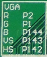
VGA
Mini USB
- Do not connect power cable if Mini-USB is connected
- CH340 USB to serial I/F
J2 - LCD
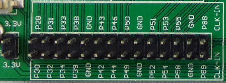
I/O Connector
JTAG
Jumpers
J1
- 1x3 shunt
- LCD Power 3.3V or 5V
J3 - LCD Type Select
Switches
DIP Switch
K1
K2
K3
K4
K5 - Marked DEV-OE
LEDs
Ring LEDs
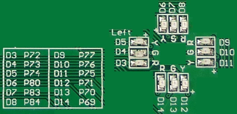
- D15 - CH340 USB Rx (in to card)
- D16 - CH340 USB Tx (out of card)
RTS/CTS Rework
- Add hardware handshake but lose 2 LEDs
- LEDs have no series resistors and count on the output drive from the FPGA (bad idea)
- Measured 1.8V on LED while lit
- Board uses CH340 USB to Serial I/F
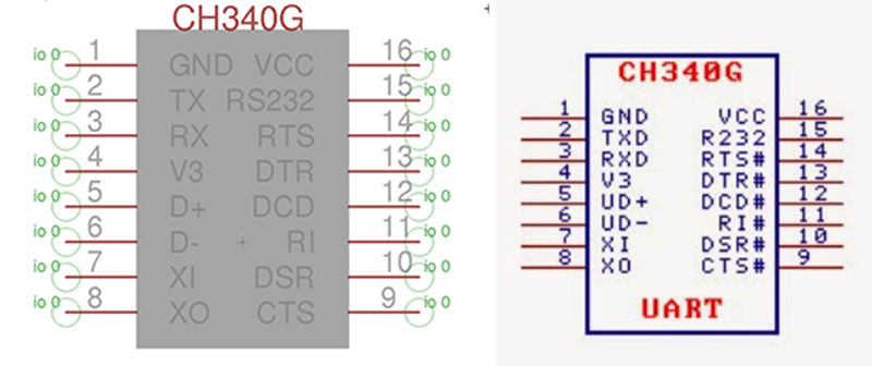
- Hardware handshakes are in the CH340G IC but not wired to the FPGA pins on the board
- This is an issue for slower serial emulations which need to throttle the host CPU
- Remove LEDs D13, D14
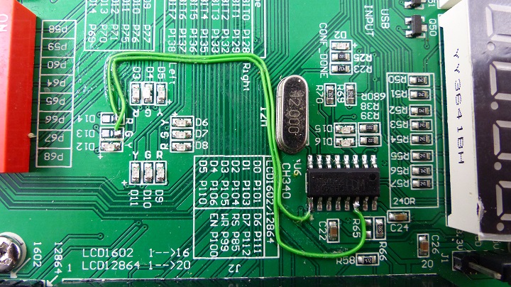
- Add wire D14 (top side) to U6-9 (CTS) (FPGA to CH340)
- Add wire D13 (top side) to U6-14 (RTS) (CH340 to FPGA )
Programming the FPGA EEPROM
- In Quartus II select File
- Convert Programming File
- Configuration Device = EPCS16
- Mode = Active Serial
- Programming File Type: *.jic
- Advanced = Check both Disables...
- Select Flash Loader
- Add Device = Cyclone IV E and EP4CE10
- Select SOF Data
- Select Add File and select the .sof file
- Generate
- In Tools, Programmer
- Add file and select the .jic file
- Select Program/Configure
- Takes a while to program
- Press nConfig button below VGA
Pin List
# Clock, Reset
set_location_assignment PIN_23 -to i_clk
set_location_assignment PIN_86 -to i_n_reset
# Serial Port
set_location_assignment PIN_114 -to i_rxd
set_location_assignment PIN_113 -to o_txd
set_location_assignment PIN_70 -to i_cts
set_location_assignment PIN_69 -to o_rts
# PS/2 Keyboard
set_location_assignment PIN_11 -to i_ps2Clk
set_location_assignment PIN_10 -to i_ps2Data
# Buzzer
set_location_assignment PIN_141 -to o_BUZZER
# Switches
set_location_assignment PIN_87 -to i_pbutton[0]
set_location_assignment PIN_91 -to i_pbutton[2]
set_location_assignment PIN_90 -to i_pbutton[1]
set_location_assignment PIN_58 -to i_DipSw[0]
set_location_assignment PIN_59 -to i_DipSw[1]
set_location_assignment PIN_60 -to i_DipSw[2]
set_location_assignment PIN_64 -to i_DipSw[3]
set_location_assignment PIN_65 -to i_DipSw[4]
set_location_assignment PIN_66 -to i_DipSw[5]
set_location_assignment PIN_67 -to i_DipSw[6]
set_location_assignment PIN_68 -to i_DipSw[7]
# LEDs
set_location_assignment PIN_72 -to o_LED[0]
set_location_assignment PIN_73 -to o_LED[1]
set_location_assignment PIN_74 -to o_LED[2]
set_location_assignment PIN_80 -to o_LED[3]
set_location_assignment PIN_83 -to o_LED[4]
set_location_assignment PIN_84 -to o_LED[5]
set_location_assignment PIN_77 -to o_LED[6]
set_location_assignment PIN_76 -to o_LED[7]
set_location_assignment PIN_75 -to o_LED[8]
set_location_assignment PIN_71 -to o_LED[9]
# Video
set_location_assignment PIN_144 -to o_Vid_Blu
set_location_assignment PIN_1 -to o_Vid_Grn
set_location_assignment PIN_2 -to o_Vid_Red
set_location_assignment PIN_142 -to o_Vid_hSync
set_location_assignment PIN_143 -to o_Vid_vSync
# Seven Segment LEDs
set_location_assignment PIN_128 -to o_Anode_Act[0]
set_location_assignment PIN_129 -to o_Anode_Act[1]
set_location_assignment PIN_132 -to o_Anode_Act[2]
set_location_assignment PIN_133 -to o_Anode_Act[3]
set_location_assignment PIN_135 -to o_Anode_Act[4]
set_location_assignment PIN_136 -to o_Anode_Act[5]
set_location_assignment PIN_137 -to o_Anode_Act[6]
set_location_assignment PIN_138 -to o_Anode_Act[7]
set_location_assignment PIN_127 -to o_LED7Seg[0]
set_location_assignment PIN_126 -to o_LED7Seg[1]
set_location_assignment PIN_125 -to o_LED7Seg[2]
set_location_assignment PIN_124 -to o_LED7Seg[3]
set_location_assignment PIN_121 -to o_LED7Seg[4]
set_location_assignment PIN_120 -to o_LED7Seg[5]
set_location_assignment PIN_119 -to o_LED7Seg[6]
set_location_assignment PIN_115 -to o_LED7Seg[7]


