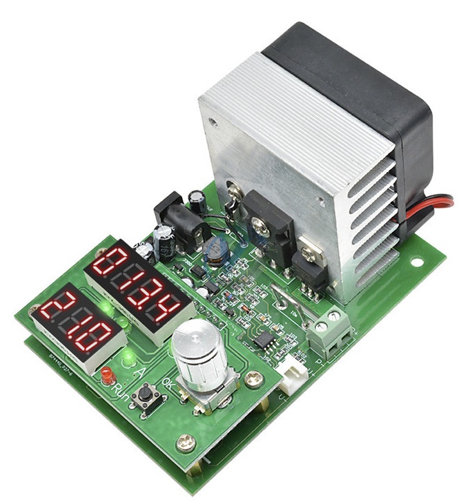
60W Constant Current Electronic Load Battery Capacity Tester
Revision as of 17:07, 24 June 2020 by Blwikiadmin (talk | contribs) (→The battery capacity test mode)
Contents
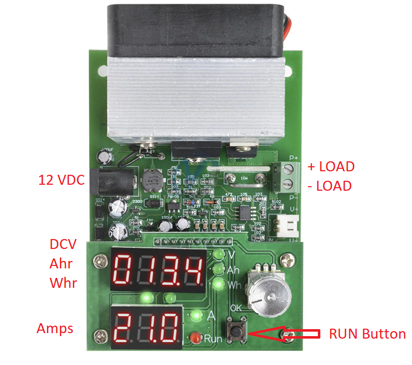
DC Power Supply
- Unit Requires 12 VDC voltage
- 0.5A min
- DC Power jack on left side
Operating Modes
- Operating modes: single mode constant current (CC)
- Discharge current : 0.20-9.99A stepper 0.1A or0.01A
- Discharge current maximum error : 0.7% -0.01A
- The maximum capacity test error : 0.5A 2.5%, 2A 1.5%, 5A and above 1.2%
- Offline ( termination ) Voltage Range : 1.0-25.0V stepping 1V or 0.1V
- Discharge voltage : 1.00-30.00V
- The maximum voltage measurement error : 1% + - 0.02V
- Maximum power : 60W super power automatically limits the maximum current (for example, up to 60W when it can open 9.99A 6V and 20V maximum at the only open 3.00A)
- Highest battery test statistic : 999.9Ah or 9999Wh, achieve value stop testing ( first value to those who stop condition )
- Board size : 60W 100mm * 70mm * 57mm ( fan prominent board about 12mm)
- Positioning hole locations : 60mm * 88mm diameter 3.2mm 5mm pedestal already installed.
- Fan control : intelligent fan control ( according to the radiator fan can be infinitely variable automatic temperature )
- Protection: Overheat protection "otP"; transient overpower protection "oPP"; overpressure protection "ouP"; reverse polarity protection; power supply voltage abnormal protection.
Setting Digital Illustration
Electronic Load mode
- Turn on the power supply 12V
- Unit will boot into electronic load mode, ensuring in a stopped state
- "RUN" does not light, otherwise the press of the start-stop switch to turn off the load
- Connect the UUT test to the (P + P -) pins - pay attention not to take the wrong polarity
- Adjust the current and lower voltage knob
- Press the knob to change the setting digit, digital middle two digits to the right of the indicator and digital indicator VA simultaneously determine the current set position .
- Press the start-stop switch , load will be applied,
- "RUN" lights
- Upper display the actual input load voltage
- If the voltage drops below the set limit voltage " RUN " LED flashes and short beep alarm buzzer beeps
The battery capacity test mode
- The test battery should be fully charged
- Set the tester in the battery capacity test mode
- Connect the battery current line to P + P- positive and negative terminals
- If you use four-wire clamp test, connect the four-wire interface to the positive and negative to the V + V - port.
- Turn the knob to set the discharge current and discharge voltage
- One press after setting the start and stop switch , a battery tester and a first line detection, automatic identification 2-4 line ( 2-wire line identification presentation JS-2,4 identification JS-4, if an error please stop the test and check the wiring ) , then enter the test , if the fault code appears , refer to later explain .
- The testing process will round up digital noticeable battery voltage , current , and the current discharge capacity Ah discharge energy Wh, when the discharge end ( battery voltage is below the set voltage ) , the tester displays the data stays in Ah and blink rapidly , with bee shortness buzzer alarm.
- Press the start and stop at the knob or switch to stop the alarm , you can turn the knob to view the battery discharge data , including discharge capacity Ah, Wh and discharge energy platform voltage V, start-stop button is pressed again, clear the data back to the initial setting interface before testing the next section batteries.
Additional information
- Battery test process can adjust the discharge current, if you need to re- adjust the termination voltage, you can pause by pressing the switch at the start and stop the discharge modification ( pause discharge will return to the settings page, this time discharge data is not lost, if necessary, you can long press clears the data until the start-stop switch 0.000Ah).
- Tester automatic storage can record setting parameters , and record all parameters and status at the end of the test process and test power failure alarm status , re- transmission of all automatically restored.
Fault protection codes and meanings
- Err1: ultra-high capacity test the battery voltage.
- Err2: battery voltage is below the set termination voltage is not connected to the battery or the battery is reversed.
- Err3: line resistance is too large or the battery can not afford to set the discharge current.
- Err4: circuit failure.
- Err6: working power is inappropriate , use a standard 12V power supply , and the supply current is not less than 0.5A.
- otP: overheating protection.
- Ert: temperature sensor failure or the temperature is too low.
- ouP: ultra-high voltage electron -load mode.
- oPP: under ultra-high power electronic load mode instantly.

