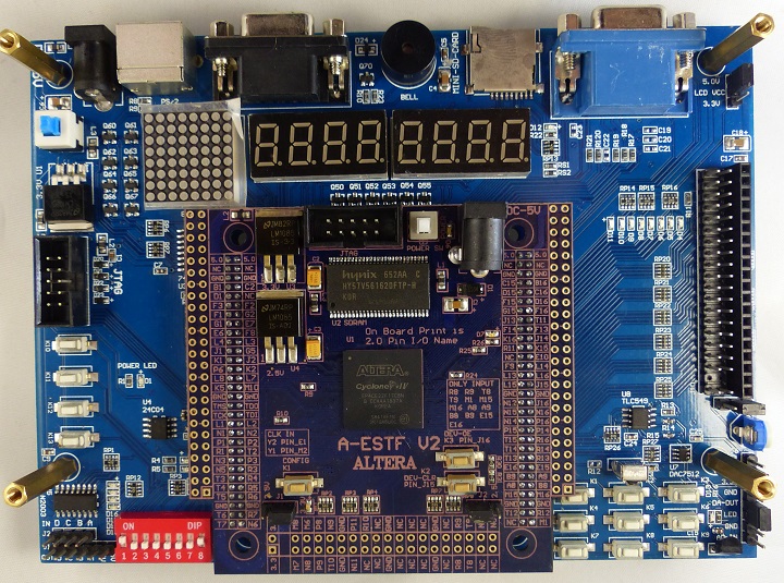
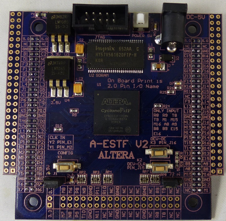
A-ESTF V2 EP4CE22 Board
Revision as of 12:14, 2 March 2021 by Blwikiadmin (talk | contribs) (→LCD (J5) and I/O (J9) Connector)
- This card was on the market for a while but has been hard to find lately (2020-01).
Contents
Core Board Features
- Board DC5V input
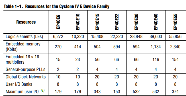
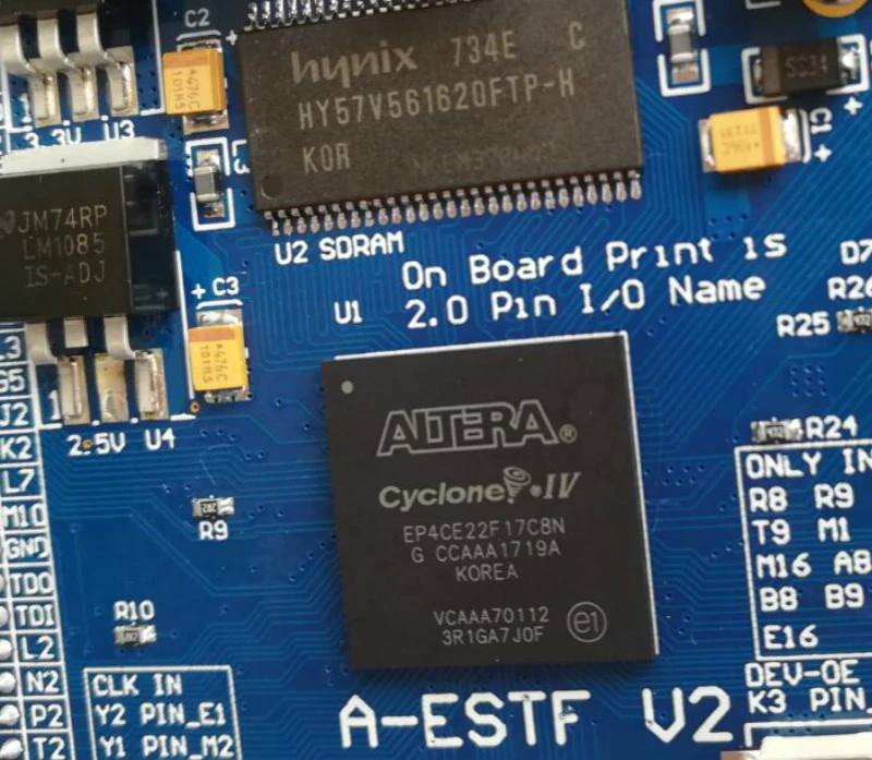
- FPGA:EP4CE22F17C8N
- SDRAM:256M bit
- SPI FLASH configuration : 64M bit
- M25P64 - use EPCS64 option in Quartus II
- 50M CLK input
- Optional crystal oscillator
- 2 pushbuttons
- Key2, Key3
- One key reconfig FPGA
- One LED output , use test board display.
- BANK1, BANK2, BANK3 VCCIO
- J1 sets 2.5V or 3.3V,
- BANK4, BANK5, BANK6 VCCIO
- J2 sets 2.5V or 3.3V
- 94 I/O Pins
- 13 of the pins are input only
Resources
FPGA Daughtercard
FPGA
- FPGA is a EP4CE22F17C8N
I/O Conns
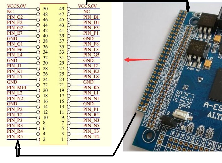
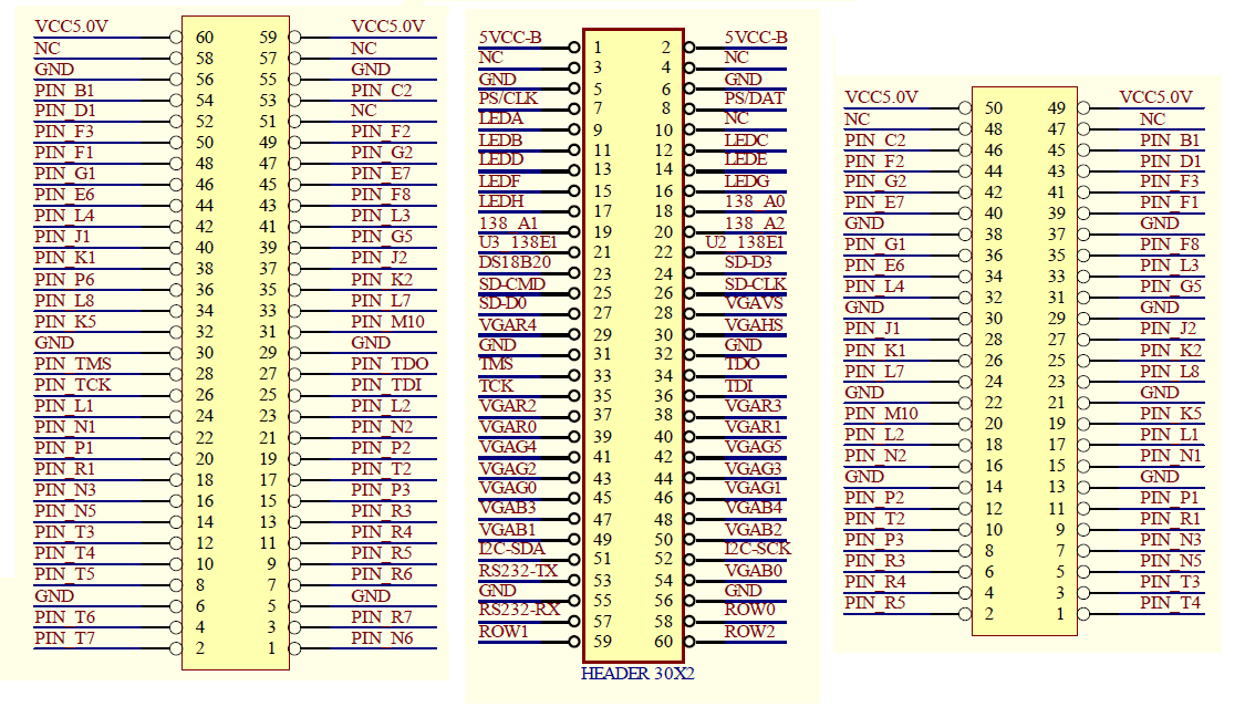
Left I/O Connector
| 60Pin | Pin (0.1") | FPGA_Pin | Function | 60Pin | Pin (0.1") | FPGA_Pin | Function | |
|---|---|---|---|---|---|---|---|---|
| 1 | 49 | 5V | Power | 2 | 50 | 5V | Power | |
| 3 | 47 | NC | 4 | 48 | NC | |||
| 5 | 37 | GND | Power | 6 | 38 | GND | Power | |
| 7 | 45 | PIN_B1 | ps2kbd_clk | 8 | 46 | PIN_C2 | ps2kbd_dat | |
| 9 | PIN_D1 | segdata[0] | 10 | NC | NC | |||
| 11 | PIN_F3 | segdata[1] | 12 | 44 | PIN_F2 | segdata[2] | ||
| 13 | PIN_F1 | segdata[3] | 14 | 42 | PIN_G2 | segdata[4] | ||
| 15 | 36 | PIN_G1 | segdata[5] | 16 | 40 | PIN_E7 | segdata[6] | |
| 17 | 34 | PIN_E6 | segdata[7] | 18 | 35 | PIN_F8 | U2_138_A[0] | |
| 19 | 32 | PIN_L4 | U2_128_A[1] | 20 | 33 | PIN_L3 | U2_138_A[2] | |
| 21 | 28 | PIN_J1 | U3_138_select | 22 | 31 | PIN_G5 | U2_138_select | |
| 23 | 26 | PIN_K1 | ds1820_dq | 24 | PIN_J2 | SD-D3/SDCS | ||
| 25 | 27 | PIN_P6 | SD-CMD/Sdin/MOSI | 26 | 25 | PIN_K2 | SDCS/SD-CLK | |
| 27 | 23 | PIN_L8 | SD-D0/Sdout/MISO | 28 | 24 | PIN_L7 | vga_vs | |
| 29 | 19 | PIN_K5 | vga_r[4] | 30 | 20 | PIN_M10 | vga_hs | |
| 31 | 13 | GND | Power | 32 | 14 | GND | Power | |
| 33 | PIN_TMS | TMS | 34 | TDO | TDO | |||
| 35 | PIN_TCK | TCK | 36 | TDI | TDI | |||
| 37 | 17 | PIN_L1 | vga_r[2] | 38 | 18 | PIN_L2 | vga_r[3] | |
| 39 | 15 | PIN_N1 | vga_r[0] | 40 | 16 | PIN_N2 | vga_r[1] | |
| 41 | 11 | PIN_P1 | vga_g[4] | 42 | 12 | PIN_P2 | vga_g[5] | |
| 43 | 9 | PIN_R1 | vga_g[2] | 44 | 10 | PIN_T2 | vga_g[3] | |
| 45 | 7 | PIN_N3 | vga_g[0] | 46 | 8 | PIN_P3 | vga_g[1] | |
| 47 | 5 | PIN_N5 | vga_b[3] | 48 | 6 | PIN_R3 | vga_b[4] | |
| 49 | 3 | PIN_T3 | vga_b[1] | 50 | 4 | PIN_R4 | vga_b[2] | |
| 51 | 1 | PIN_T4 | I2C-SDA | 52 | 2 | PIN_R5 | I2C_SCL | |
| 53 | PIN_T3 | RS232-TX | 54 | PIN_R6 | vga_b[0] | |||
| 55 | 21 | GND | Power | 56 | 22 | GND | Power | |
| 57 | PIN_T6 | RS232-RX | 58 | PIN_R7 | ROW0 | |||
| 59 | PIN_T7 | ROW1 | 60 | PIN_N6 | ROW2 | |||
| 29 | GND | Power | 30 | GND | Power |
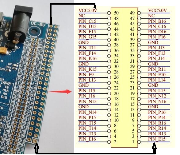
Right I/O Connector
| 60Pin | 50Pin | FPGA_Pin | Function | J10 | X | 60Pin | 50Pin | FPGA_Pin | Function | J10 |
|---|---|---|---|---|---|---|---|---|---|---|
| 60 | 50 | 5V | Power | 59 | 49 | 5V | Power | |||
| 58 | 48 | NC | 57 | 47 | NC | |||||
| 56 | 38 | GND | Power | 55 | 37 | GND | Power | |||
| 54 | 46 | PIN_C15 | Buzzer/BELL | 53 | 45 | PIN_B16 | LED[7]/LED14 | |||
| 52 | 44 | PIN_D15 | LED[6]/LED13 | 51 | 43 | PIN_C16 | LED[5]/LED9 | |||
| 50 | 42 | PIN_F15 | LED[4]/LED8 | 49 | 41 | PIN_D16 | LED[3]/LED7 | |||
| 48 | 40 | PIN_G15 | LED[2]/LED6 | 47 | 39 | PIN_F16 | LED[1]/LED5 | |||
| 46 | 35 | PIN_J13 | LED[0]/LED4 | 45 | 36 | PIN_T11 | IO0 | 34 | ||
| 44 | 34 | PIN_F14 | IO1 | 32 | 43 | 33 | PIN_F13 | LCDdat[7]/IO2 | 33 | |
| 42 | 32 | PIN_K16 | IO3 | 28 | 41 | 31 | PIN_J14 | LCDdat[6]/IO4 | 31 | |
| 40 | 27 | PIN_R11 | IO5 | 27 | 39 | 28 | PIN_K15 | LCDdat[5]/IO6 | 26 | |
| 38 | NC | 37 | 25 | PIN_E10 | IO7 | 25 | ||||
| 36 | 26 | PIN_F9 | LCDdat[4]/IO8 | 24 | 35 | 23 | PIN_L14 | IO9 | 23 | |
| 34 | 24 | PIN_L13 | LCDdat[3]/IO10 | 33 | PIN_L16 | IO11 | ||||
| 32 | 19 | PIN_L15 | LCDdat[2]/IO12 | 18 | 31 | 20 | PIN_J15 | rst/IO13 | 20 | |
| 30 | 14 | GND | Power | 14 | 29 | 13 | GND | Power | 13 | |
| 28 | 17 | PIN_N12 | LCDdat[1]/IO14 | 16 | 27 | 18 | PIN_J16 | resetbtn/IO15 | 18 | |
| 26 | 16 | PIN_N15 | LCDdat[0]/IO16 | 12 | 25 | 15 | PIN_N16 | IO17 | 15 | |
| 24 | 12 | PIN_N14 | LCDen/IO18 | 10 | 23 | 11 | PIN_P16 | IO19 | 11 | |
| 22 | 10 | PIN_P15 | rw/LCDWR/IO20 | 8 | 21 | 9 | PIN_P14 | IO21 | 9 | |
| 20 | 8 | PIN_T15 | LCDrs/IO22 | 6 | 19 | 7 | PIN_R16 | IO23 | 7 | |
| 18 | 6 | PIN_T14 | cs/ADCS | 17 | 5 | PIN_R14 | A2DData | |||
| 16 | 4 | PIN_T13 | ioclk/ADCLK | 15 | 3 | PIN_R13 | da_data | |||
| 14 | 2 | PIN_E16 | row[2]/COL2 | 13 | 1 | PIN_E15 | row[1]/COL1 | |||
| 12 | PIN_B9 | SW6 | 11 | PIN_A9 | COL0 | |||||
| 10 | PIN_A8 | K14/SW4 | 9 | PIN_B8 | K12/SW3 | |||||
| 8 | PIN_M15 | K11/SW2 | 7 | PIN_M16 | K10/SW1 | |||||
| 6 | GND | 5 | GND | GND | ||||||
| 4 | PIN_T12 | DA-SCLK | 3 | PIN_R12 | DA-SYNC | |||||
| 2 | NC | 1 | CLK_M1 | IR_INPUT | ||||||
| 30 | GND | Power | 30 | 29 | GND | Power | 29 | |||
| 22 | GND | Power | 21 | GND | Power |
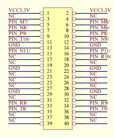
Front I/O Connector
| 40Pin | FPGA_Pin | Function | 40Pin | FPGA_Pin | Function | |
|---|---|---|---|---|---|---|
| 1 | 5V | Power | 2 | 5V | Power | |
| 3 | NO_PIN | 4 | NO_PIN | |||
| 5 | GND | Power | 6 | GND | Power | |
| 7 | PIN_M7 | 8 | PIN_M8 | |||
| 9 | PIN_N8 | 10 | PIN_M6 | |||
| 11 | PIN_P9 | 12 | PIN_P8 | |||
| 13 | PIN_T10 | 14 | PIN_N9 | |||
| 15 | GND | 16 | GND | |||
| 17 | PIN_N11 | 18 | PIN_P11 | |||
| 19 | NC | 20 | PIN_R10 | |||
| 21 | NC | 22 | NC | |||
| 23 | GND | 24 | GND | |||
| 25 | NC | 26 | NC | |||
| 27 | NC | 28 | NC | |||
| 29 | NC | 30 | NC | |||
| 31 | GND | 32 | GND | |||
| 33 | NC | 34 | NC | |||
| 35 | PIN_R8 | 36 | PIN_R9 | |||
| 37 | PIN_T8 | 38 | PIN_T9 | |||
| 39 | NC | 40 | NC | |||
| 41 | NC | 42 | NC |
Interfaces
Clocks
- Y1 = PIN_M2
- CLK_50M = PIN_E1
EPCS Configuration EEPROM
- EPCS_CS = PIN_D2
- EPCS_DATA0 = PIN_H2
- EPCS_DCLK = PIN_H1
- EPCS_SDO = PIN_C1
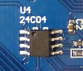
24C04 EEPROM
- PIN_R5 = I2C_SCL
- PIN_T4 = I2C-SDA
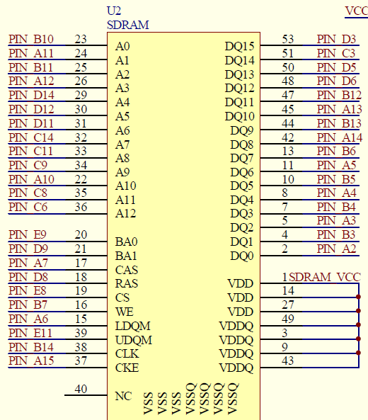
SDRAM
- SDR_AD[12] Bidir PIN_C6
- SDR_AD[11] Bidir PIN_C8
- SDR_AD[10] Bidir PIN_A10
- SDR_AD[9] Bidir PIN_C9
- SDR_AD[8] Bidir PIN_C11
- SDR_AD[7] Bidir PIN_C14
- SDR_AD[6] Bidir PIN_D11
- SDR_AD[5] Bidir PIN_D12
- SDR_AD[4] Bidir PIN_D14
- SDR_AD[3] Bidir PIN_A12
- SDR_AD[2] Bidir PIN_B11
- SDR_AD[1] Bidir PIN_A11
- SDR_AD[0] Bidir PIN_B10
- SDR_BA[1] Bidir PIN_D9
- SDR_BA[0] Bidir PIN_E9
- SDR_CAS Bidir PIN_A7
- SDR_CKE Bidir PIN_A15
- SDR_CLK Bidir PIN_B14
- SDR_CS Bidir PIN_E8
- SDR_DA[15] Bidir PIN_D3
- SDR_DA[14] Bidir PIN_C3
- SDR_DA[13] Bidir PIN_D5
- SDR_DA[12] Bidir PIN_D6
- SDR_DA[11] Bidir PIN_B12
- SDR_DA[10] Bidir PIN_A13
- SDR_DA[9] Bidir PIN_B13
- SDR_DA[8] Bidir PIN_A14
- SDR_DA[7] Bidir PIN_B6
- SDR_DA[6] Bidir PIN_A5
- SDR_DA[5] Bidir PIN_B5
- SDR_DA[4] Bidir PIN_A4
- SDR_DA[3] Bidir PIN_B4
- SDR_DA[2] Bidir PIN_A3
- SDR_DA[1] Bidir PIN_B3
- SDR_DA[0] Bidir PIN_A2
- SDR_DQM[1] Bidir PIN_E11
- SDR_DQM[0] Bidir PIN_A6
- SDR_RAS Bidir PIN_D8
- SDR_WE Bidir PIN_B7
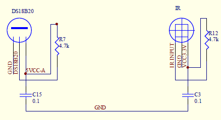
DS1820 Temp / IR Sensors
- CLK_M1 = IR_INPUT
- PIN_K1 = DS1820_dq
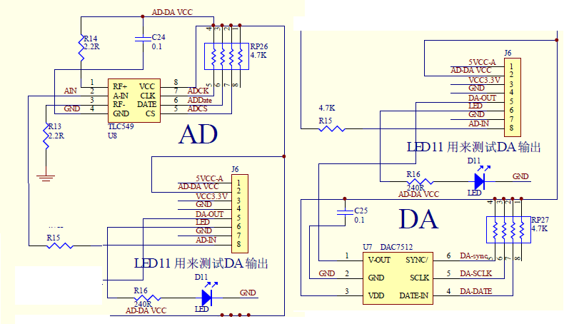
A/D and D/A Converters
- PIN_R12 = DA-SYNC
- PIN_T12 = DA-SCLK
- PIN_R13 = da_data
- PIN_R14 = A2DData
- PIN_T13 = ADCLK
- PIN_T14 = ADCS
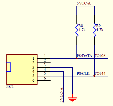
PS/2 Connector
- PIN_B1 = ps2kbd_clk
- PIN_C2 = ps2kbd_dat
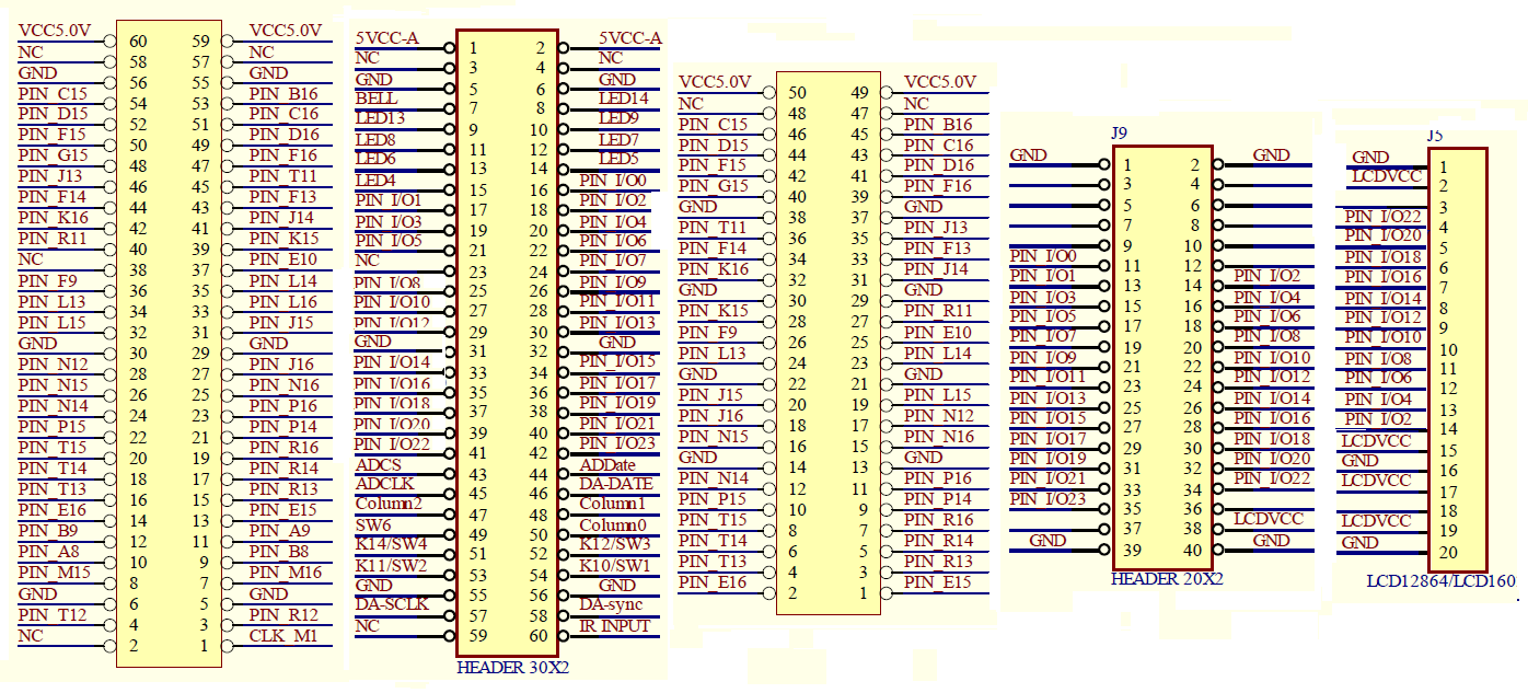
LCD (J5) and I/O (J9) Connector
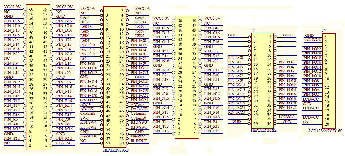
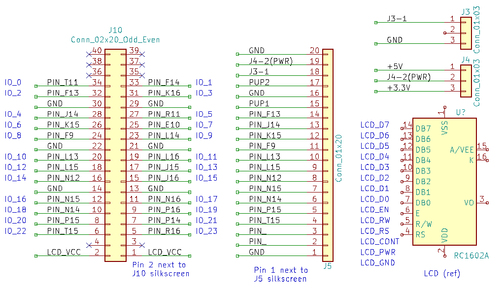
- The manufacturer schematic (that I found) does not match the connections below
- J5 is a 1x20 pin female connector intended to be used with a "standard" 1602 LCD
- Pin 1 (see schematic below) is adjacent to the J5 silkscreen
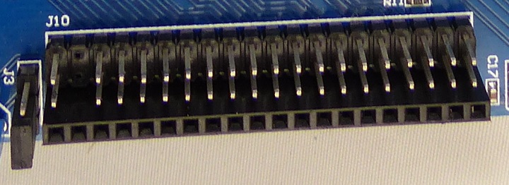
- J10 is a 2x20 pin male header
- Pin 2 (see schematic below) is adjacent to the J10 silkscreen
- This is a partial schematic of J5 and J10
J4
- J4 is the voltage selector for the J5 LCD connector
- My board has 50 ohm resistors between the FPGA and J5/J10 connections
- Pinout
- 1-2 = 3.3V (Use this since 50 ohms is not enough to protect inputs)
- 2-3 = 5V
J10
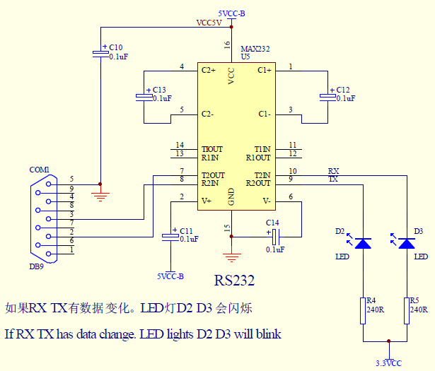
RS-232 Connector
- PIN_T3 = RS232-TX
- PIN_T6 = RS232-RX
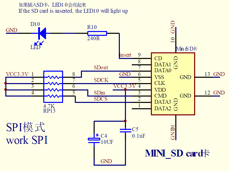
SD Card
- PIN_J2 = SD-D3/SDCS
- PIN_P6 = SD-CMD/Sdin/MOSI
- PIN_K2 = SDCS/SD-CLK
- PIN_L8 = SD-D0/Sdout/MISO
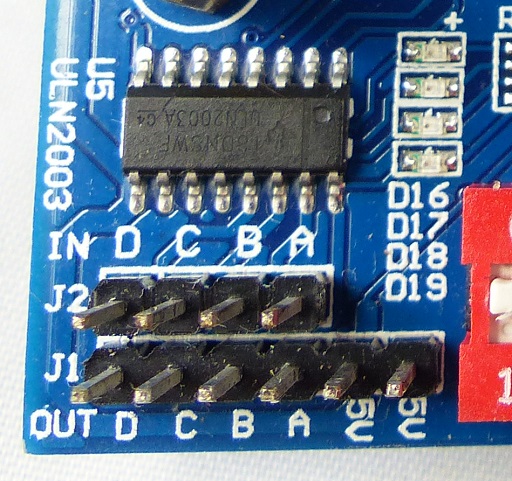
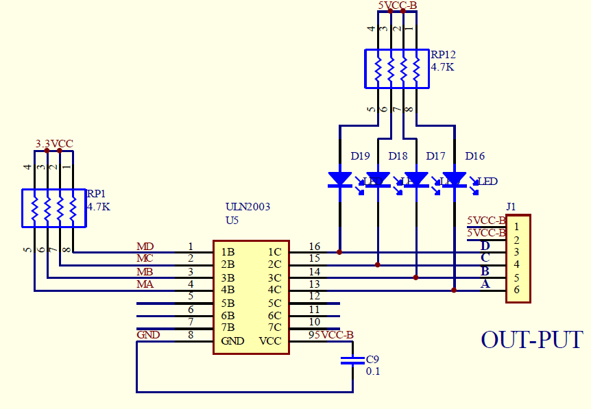
Relay/Motor Driver ULN2003
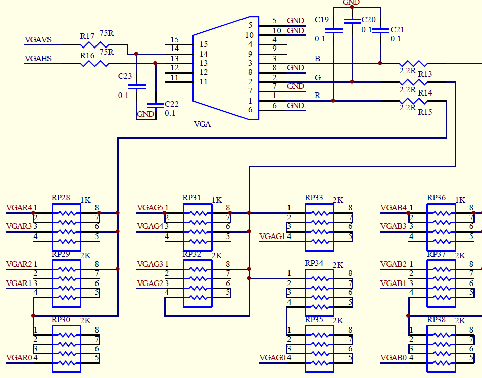
VGA Connector
- PIN_L7 = vga_vs
- PIN_M10 = vga_hs
- PIN_K5 = vga_r[4]
- PIN_L2 = vga_r[3]
- PIN_L1 = vga_r[2]
- PIN_N2 = vga_r[1]
- PIN_N1 = vga_r[0]
- PIN_P2 = vga_g[5]
- PIN_P1 = vga_g[4]
- PIN_T2 = vga_g[3]
- PIN_R1 = vga_g[2]
- PIN_P3 = vga_g[1]
- PIN_N3 = vga_g[0]
- PIN_R3 = vga_b[4]
- PIN_N5 = vga_b[3]
- PIN_R4 = vga_b[2]
- PIN_T3 = vga_b[1]
- PIN_R6 = vga_b[0]
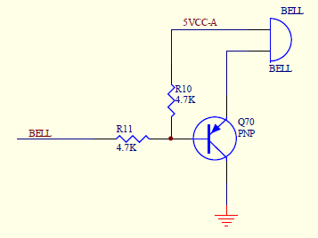
Buzzer
- PIN_C15 = Buzzer/BELL
Switches
J4
- 1-2 = 3.3V
- 2-3 = 5V
Switches on FPGA Card
- K1 = CONFIG - Reload FPGA from EEPROM
- K2 = PIN_J15 - DEV-CLR -
- K3 = PIN_J16 - DEV-OE - Reset button
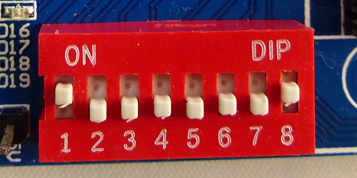
DIP Switches
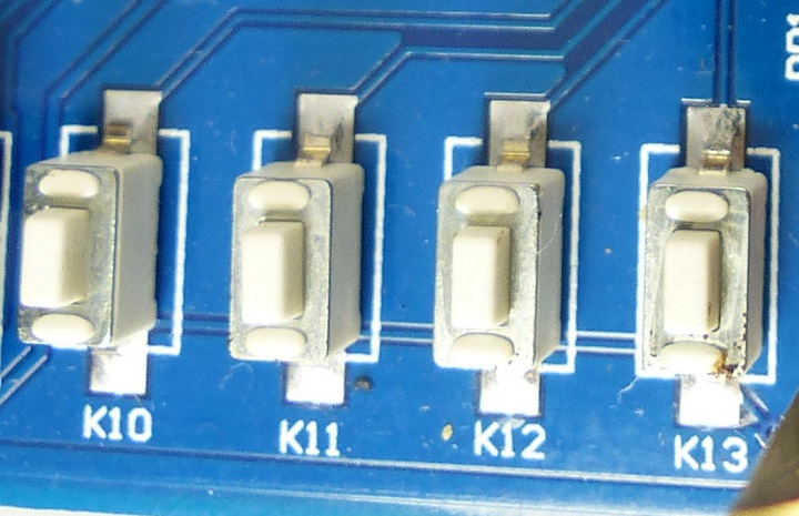
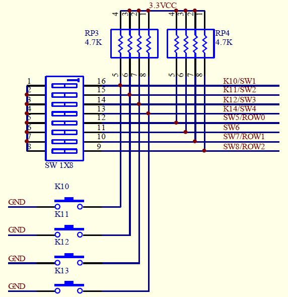
- K10/SW1 - Right conn Pin 54 - FPGA PIN_C15
- K11/SW2 - Right conn Pin 53 - FPGA PIN_
- K12/SW3 - Right conn Pin 52 - FPGA PIN_
- K14/SW4 - Right conn Pin 51 - FPGA PIN_
- SW5/ROW0 - Left conn Pin 58 - FPGA PIN_
- SW6 - Right conn Pin 49 - FPGA PIN_
- SW7/ROW1 - Left conn Pin 59 - FPGA PIN_
- SW8/ROW2 - Left conn Pin 60 - FPGA PIN_
Pushbuttons
Pushbuttons
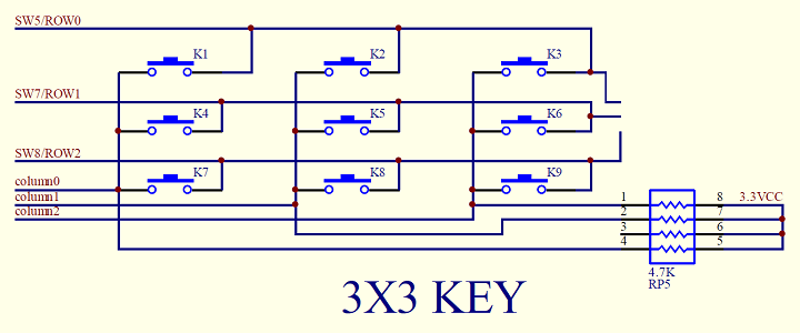
- DIP_SW_5 = PIN_R7 (ROW0)
- DIP_SW_7 = PIN_T7 (ROW1)
- DIP_SW_8 = PIN_N6 (ROW2)
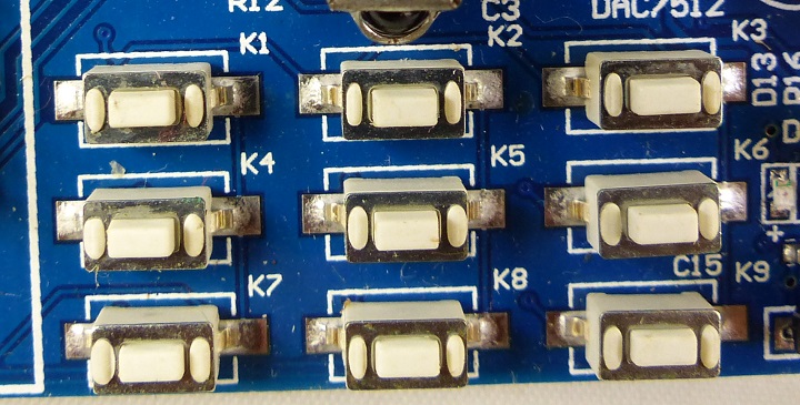
3x3 Switch Array
LEDs
LED on FPGA Card
- LED_D8 = PIN_M8
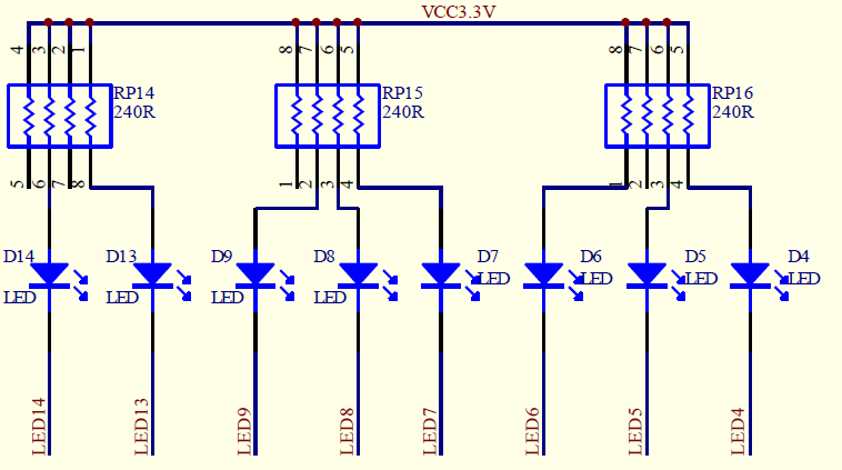
8 LEDs
- PIN_B16 = LED11 (LED14 on schematic)
- PIN_D15 = LED10 (LED13 on schematic)
- PIN_C16 = LED9
- PIN_F15 = LED8
- PIN_D16 = LED7
- PIN_G15 = LED6
- PIN_F16 = LED5
- PIN_J13 = LED4
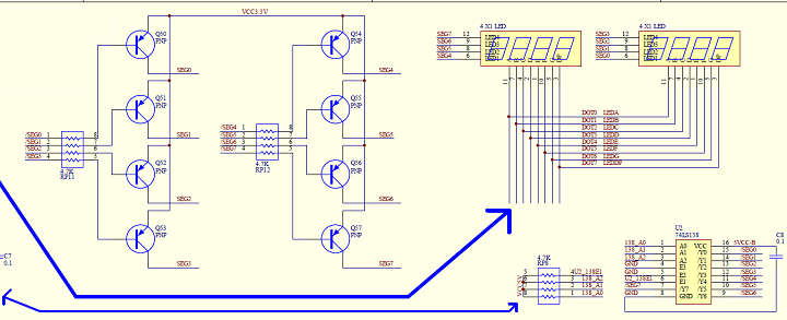
Seven Segment Display
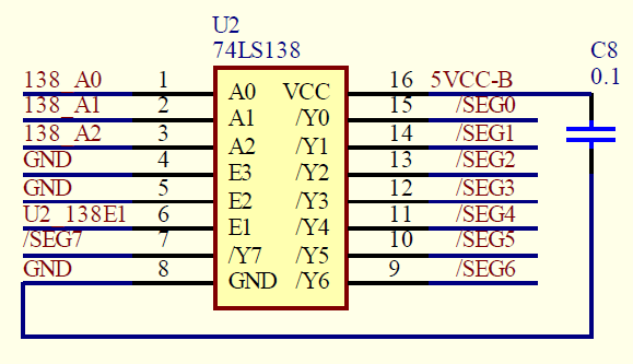
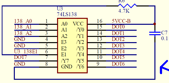
- PIN_F8 = U2_138_A[0]
- PIN_L4 = U2_128_A[1]
- PIN_L3 = U2_138_A[2]
- PIN_J1 = U3_138_select
- PIN_G5 = U2_138_select
- PIN_D1 = segdata[0]
- PIN_F3 = segdata[1]
- PIN_F2 = segdata[2]
- PIN_F1 = segdata[3]
- PIN_G2 = segdata[4]
- PIN_G1 = segdata[5]
- PIN_E7 = segdata[6]
- PIN_E6 = segdata[7]
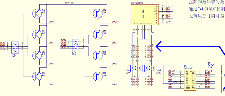
8x8 Matrix Array
- PIN_F8 = U2_138_A[0]
- PIN_L4 = U2_128_A[1]
- PIN_L3 = U2_138_A[2]
- PIN_J1 = U3_138_select
- PIN_G5 = U2_138_select
- PIN_D1 = segdata[0]
- PIN_F3 = segdata[1]
- PIN_F2 = segdata[2]
- PIN_F1 = segdata[3]
- PIN_G2 = segdata[4]
- PIN_G1 = segdata[5]
- PIN_E7 = segdata[6]
- PIN_E6 = segdata[7]
Programming permanent (download)
- If already created: Open Conversion Setup Data
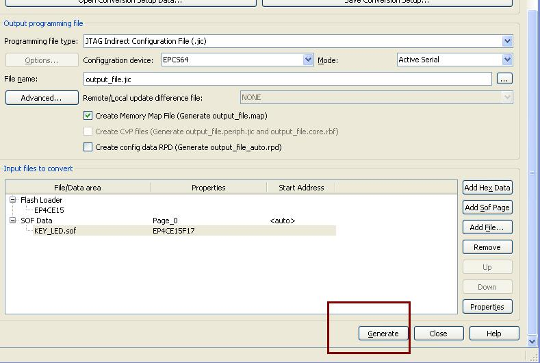
- if not yet created - procedure create file to program the EPCS64 chip
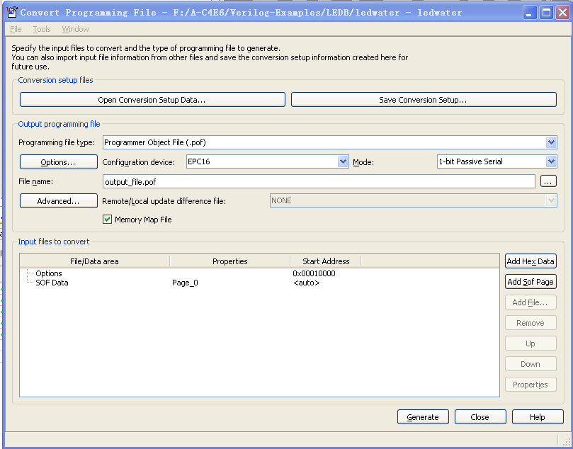
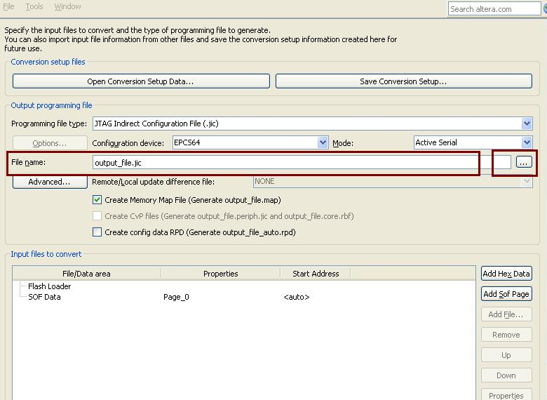
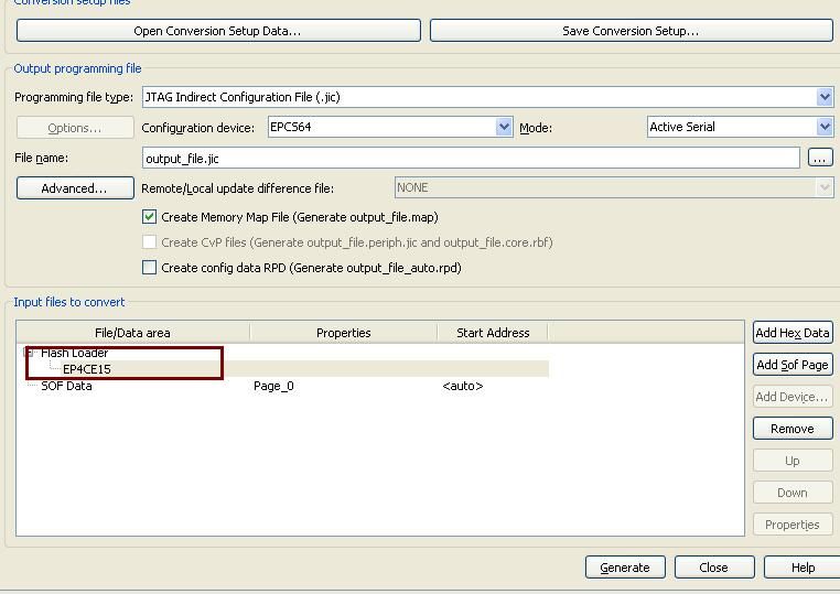
- In Quartus, File > Convert Programming File
- Looks like
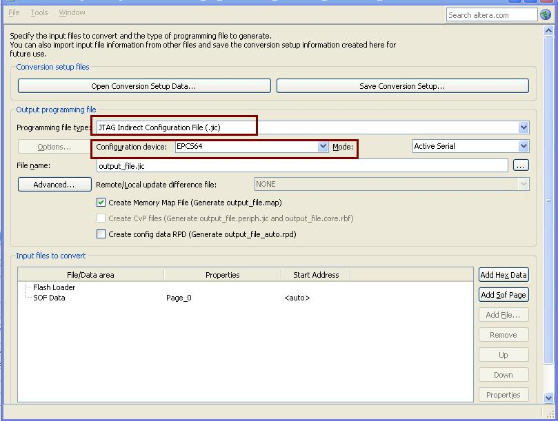
- Select [Create] Memory Map File
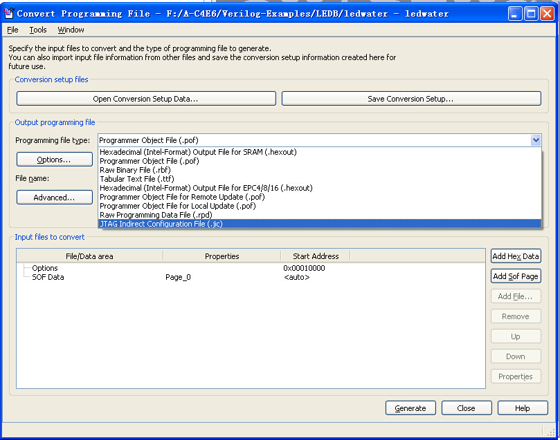
- Programming File Type: JTAG .jic
- Select: Active Serial
- Configuration device: EPCS64
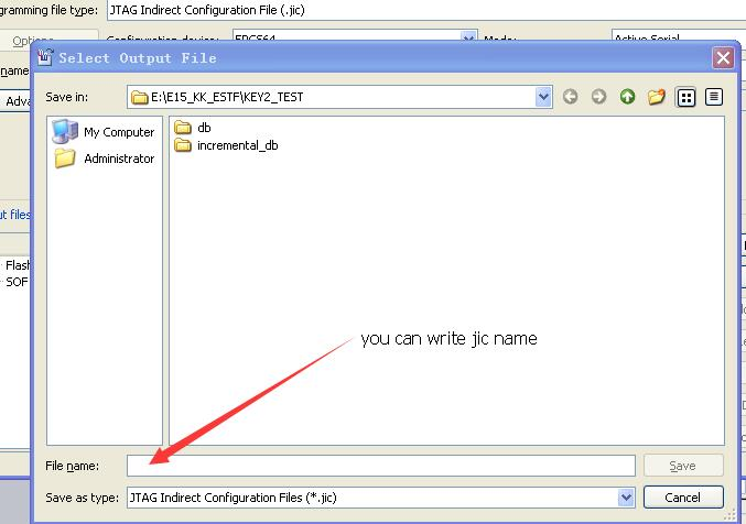
- File name: output_file.jic
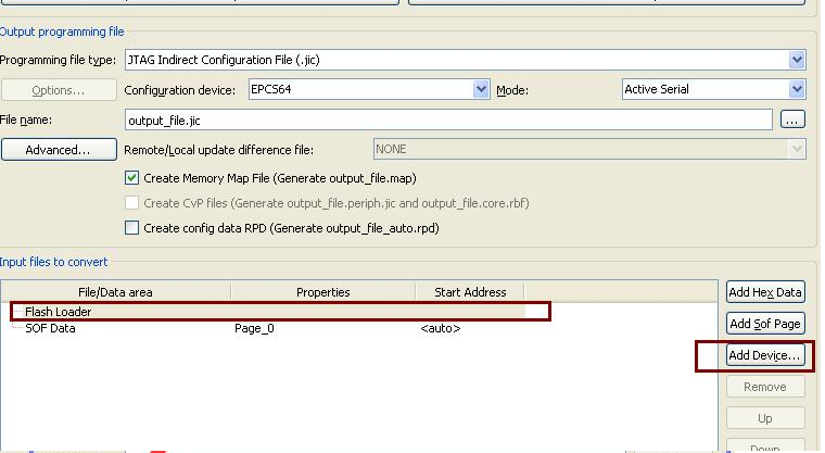
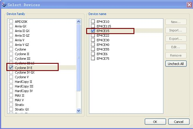
- Flash Loader
- Device Family: Cyclone IV E
- Device name: EP4CE22
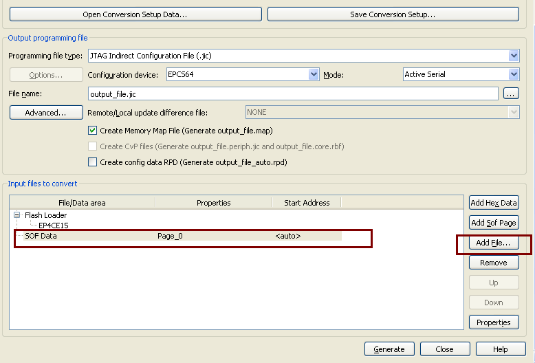
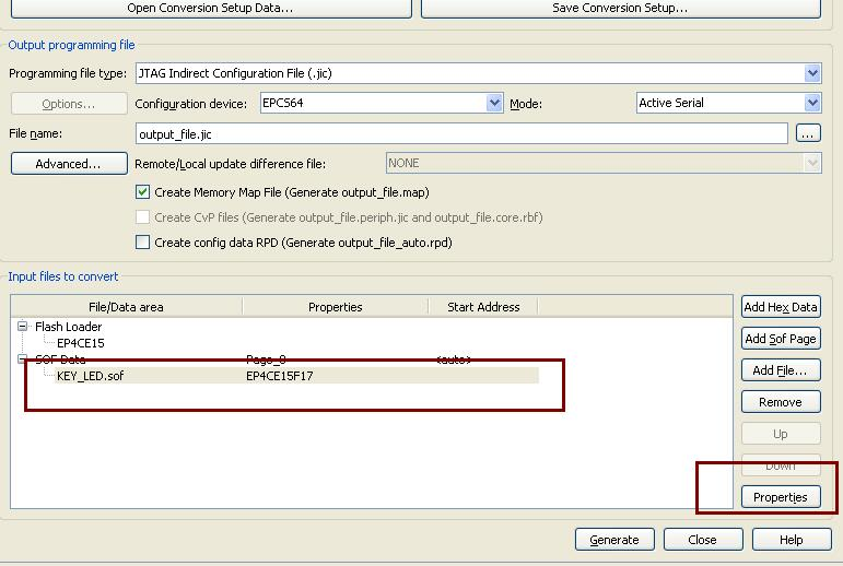
- SOF Data: TOP.SOF
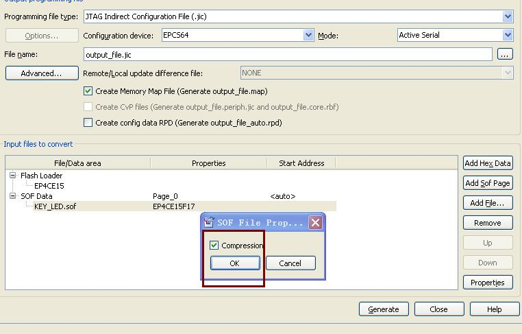
- Click top.sof > Properties: Click Compression
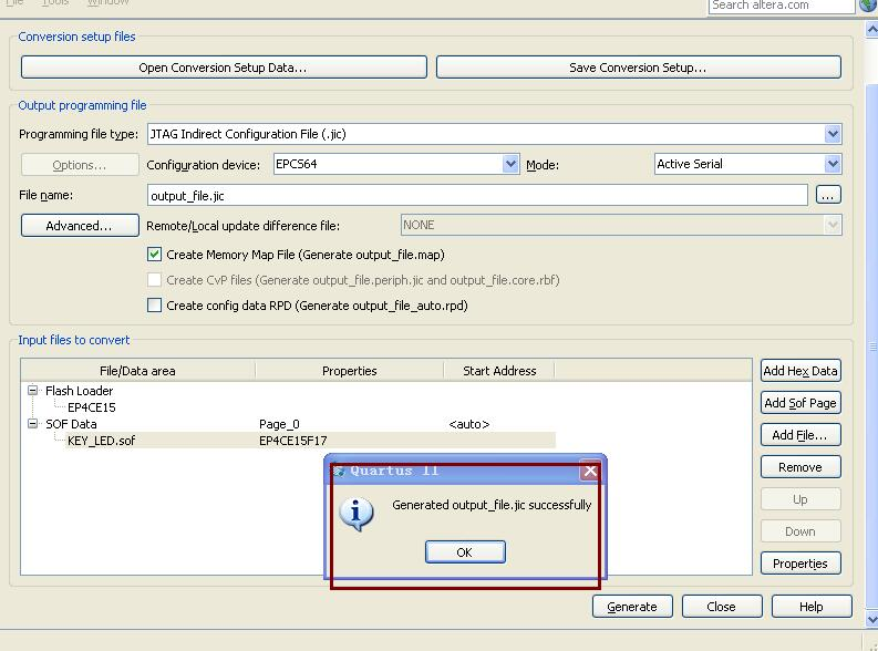
- Select Generate
- Save Conversion Setup
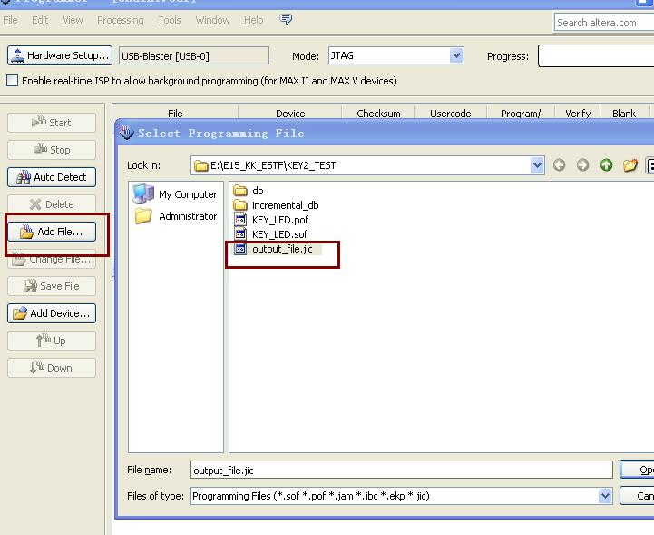
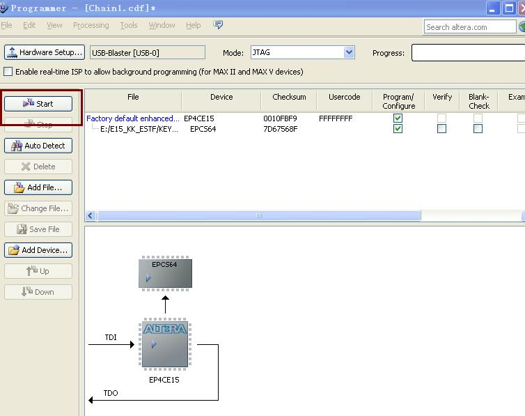
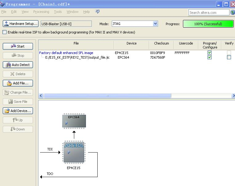
- Program Device
Pin List
set_location_assignment PIN_E1 -to CLK_50M
set_location_assignment PIN_J15 -to rst
set_location_assignment PIN_B8 -to rstn
set_location_assignment PIN_M16 -to i_rst_n
set_location_assignment PIN_C15 -to Buzzer
set_location_assignment PIN_M1 -to IR
set_location_assignment PIN_K1 -to ds1820_dq
# VGA
set_location_assignment PIN_N1 -to vga_r[0]
set_location_assignment PIN_N2 -to vga_r[1]
set_location_assignment PIN_L1 -to vga_r[2]
set_location_assignment PIN_L2 -to vga_r[3]
set_location_assignment PIN_K5 -to vga_r[4]
set_location_assignment PIN_N3 -to vga_g[0]
set_location_assignment PIN_P3 -to vga_g[1]
set_location_assignment PIN_R1 -to vga_g[2]
set_location_assignment PIN_T2 -to vga_g[3]
set_location_assignment PIN_P1 -to vga_g[4]
set_location_assignment PIN_P2 -to vga_g[5]
set_location_assignment PIN_R6 -to vga_b[0]
set_location_assignment PIN_T3 -to vga_b[1]
set_location_assignment PIN_R4 -to vga_b[2]
set_location_assignment PIN_N5 -to vga_b[3]
set_location_assignment PIN_R3 -to vga_b[4]
set_location_assignment PIN_M10 -to vga_hs
set_location_assignment PIN_L7 -to vga_vs
#
set_location_assignment PIN_G5 -to U2_138_select
set_location_assignment PIN_J1 -to U3_138_select
set_location_assignment PIN_L3 -to U2_128_A[2]
set_location_assignment PIN_L4 -to U2_128_A[1]
set_location_assignment PIN_F8 -to U2_128_A[0]
set_location_assignment PIN_L3 -to U2_138[2]
set_location_assignment PIN_L4 -to U2_138[1]
set_location_assignment PIN_F8 -to U2_138[0]
set_location_assignment PIN_A9 -to row[0]
set_location_assignment PIN_E15 -to row[1]
set_location_assignment PIN_E16 -to row[2]
set_location_assignment PIN_R7 -to col[0]
set_location_assignment PIN_T7 -to col[1]
set_location_assignment PIN_N6 -to col[2]
set_location_assignment PIN_T14 -to cs
# DAC7512
set_location_assignment PIN_R13 -to da_data_out
set_location_assignment PIN_T12 -to sclk_out
set_location_assignment PIN_R12 -to sync_out
set_location_assignment PIN_M16 -to resetin
# ADC_TLC549
set_location_assignment PIN_R14 -to data
set_location_assignment PIN_T13 -to ioclk
# Seven Segment Display
set_location_assignment PIN_D1 -to segdata[0]
set_location_assignment PIN_F3 -to segdata[1]
set_location_assignment PIN_F2 -to segdata[2]
set_location_assignment PIN_F1 -to segdata[3]
set_location_assignment PIN_G2 -to segdata[4]
set_location_assignment PIN_G1 -to segdata[5]
set_location_assignment PIN_E7 -to segdata[6]
set_location_assignment PIN_E6 -to segdata[7]
set_location_assignment PIN_M8 -to LED_D8
# Switches and LEDs
set_location_assignment PIN_A8 -to key1
set_location_assignment PIN_J16 -to key_in
set_location_assignment PIN_M16 -to switch[0]
set_location_assignment PIN_M15 -to switch[1]
set_location_assignment PIN_B8 -to switch[2]
set_location_assignment PIN_A8 -to switch[3]
set_location_assignment PIN_A9 -to switch[4]
set_location_assignment PIN_B9 -to switch[5]
set_location_assignment PIN_E15 -to switch[6]
set_location_assignment PIN_E16 -to switch[7]
set_location_assignment PIN_J13 -to LED[0]
set_location_assignment PIN_F16 -to LED[1]
set_location_assignment PIN_G15 -to LED[2]
set_location_assignment PIN_D16 -to LED[3]
set_location_assignment PIN_F15 -to LED[4]
set_location_assignment PIN_C16 -to LED[5]
set_location_assignment PIN_D15 -to LED[6]
set_location_assignment PIN_B16 -to LED[7]
# SDRAM
set_location_assignment PIN_D9 -to SDR_BA[1]
set_location_assignment PIN_E9 -to SDR_BA[0]
set_location_assignment PIN_B10 -to SDR_AD[0]
set_location_assignment PIN_A11 -to SDR_AD[1]
set_location_assignment PIN_B11 -to SDR_AD[2]
set_location_assignment PIN_A12 -to SDR_AD[3]
set_location_assignment PIN_D14 -to SDR_AD[4]
set_location_assignment PIN_D12 -to SDR_AD[5]
set_location_assignment PIN_D11 -to SDR_AD[6]
set_location_assignment PIN_C14 -to SDR_AD[7]
set_location_assignment PIN_C11 -to SDR_AD[8]
set_location_assignment PIN_C9 -to SDR_AD[9]
set_location_assignment PIN_A10 -to SDR_AD[10]
set_location_assignment PIN_C8 -to SDR_AD[11]
set_location_assignment PIN_C6 -to SDR_AD[12]
set_location_assignment PIN_A2 -to SDR_DA[0]
set_location_assignment PIN_B3 -to SDR_DA[1]
set_location_assignment PIN_A3 -to SDR_DA[2]
set_location_assignment PIN_B4 -to SDR_DA[3]
set_location_assignment PIN_A4 -to SDR_DA[4]
set_location_assignment PIN_B5 -to SDR_DA[5]
set_location_assignment PIN_A5 -to SDR_DA[6]
set_location_assignment PIN_B6 -to SDR_DA[7]
set_location_assignment PIN_A14 -to SDR_DA[8]
set_location_assignment PIN_B13 -to SDR_DA[9]
set_location_assignment PIN_A13 -to SDR_DA[10]
set_location_assignment PIN_B12 -to SDR_DA[11]
set_location_assignment PIN_D6 -to SDR_DA[12]
set_location_assignment PIN_D5 -to SDR_DA[13]
set_location_assignment PIN_C3 -to SDR_DA[14]
set_location_assignment PIN_D3 -to SDR_DA[15]
set_location_assignment PIN_D8 -to SDR_RAS
set_location_assignment PIN_A7 -to SDR_CAS
set_location_assignment PIN_B7 -to SDR_WE
set_location_assignment PIN_E8 -to SDR_CS
set_location_assignment PIN_A15 -to SDR_CKE
set_location_assignment PIN_B14 -to SDR_CLK
set_location_assignment PIN_A6 -to SDR_DQM[0]
set_location_assignment PIN_E11 -to SDR_DQM[1]
# EPCS
set_location_assignment PIN_D2 -to EPCS_CS
set_location_assignment PIN_H2 -to EPCS_DATA0
set_location_assignment PIN_H1 -to EPCS_DCLK
set_location_assignment PIN_C1 -to EPCS_SDO
# LED Matrix
set_location_assignment PIN_D1 -to LED_Matrix[0]
set_location_assignment PIN_F3 -to LED_Matrix[1]
set_location_assignment PIN_F2 -to LED_Matrix[2]
set_location_assignment PIN_F1 -to LED_Matrix[3]
set_location_assignment PIN_G2 -to LED_Matrix[4]
set_location_assignment PIN_G1 -to LED_Matrix[5]
set_location_assignment PIN_E7 -to LED_Matrix[6]
set_location_assignment PIN_E6 -to LED_Matrix[7]
set_location_assignment PIN_D1 -to keyboard_val[0]
set_location_assignment PIN_F3 -to keyboard_val[1]
set_location_assignment PIN_F2 -to keyboard_val[2]
set_location_assignment PIN_F1 -to keyboard_val[3]
set_location_assignment PIN_G2 -to keyboard_val[4]
set_location_assignment PIN_G1 -to keyboard_val[5]
set_location_assignment PIN_E7 -to keyboard_val[6]
set_location_assignment PIN_E6 -to keyboard_val[7]
# LCD
set_location_assignment PIN_P15 -to rw
set_location_assignment PIN_N14 -to en
set_location_assignment PIN_F13 -to dat[7]
set_location_assignment PIN_J14 -to dat[6]
set_location_assignment PIN_K15 -to dat[5]
set_location_assignment PIN_F9 -to dat[4]
set_location_assignment PIN_L13 -to dat[3]
set_location_assignment PIN_L15 -to dat[2]
set_location_assignment PIN_N12 -to dat[1]
set_location_assignment PIN_N15 -to dat[0]
set_location_assignment PIN_T15 -to rs
