Difference between revisions of "ANTUNER"
Jump to navigation
Jump to search
Blwikiadmin (talk | contribs) |
Blwikiadmin (talk | contribs) (→Layout) |
||
| Line 26: | Line 26: | ||
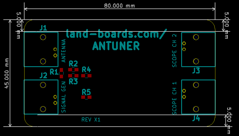
== Layout == | == Layout == | ||
| − | ANTUNER-Layout-X1.png | + | [[File:ANTUNER-Layout-X1.png]] |
== Assembly Sheet / Parts List == | == Assembly Sheet / Parts List == | ||
[[ANTUNER-X1 Assembly Sheet]] | [[ANTUNER-X1 Assembly Sheet]] | ||
Latest revision as of 15:16, 18 January 2020
Features
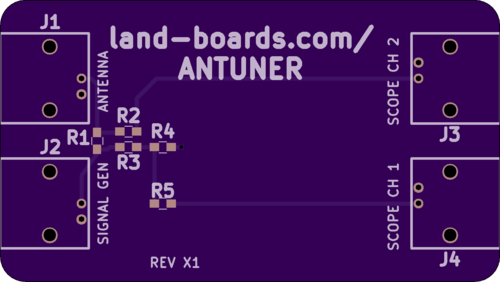
- Used to determine antenna resonant frequency
- Whetstone bridge design
- 2-Channel Scope BNC connections
- Signal Generator BNC input
- Antenna Under Test BNC connection
- Form factor matches standard 50mmx80mm extruded enclosure
- Measuring Complex Impedances
- This circuit can be used to measure complex impedance
- R2 and R5 are not critical but should be matched
- R1 and R3 should probably be 50-ish Ohms (47 Ohm should be OK)
- R4 should probably be somewhere near the nominal resistance of the load you are testing
- Scope may need to be floated depending upon the network that is being measured
W2AEW design
Youtube Video #112: Use an Oscilloscope and Signal Generator help tune an HF Antenna, measure complex impedance


