Difference between revisions of "ArduinoInABox"
Jump to navigation
Jump to search
Blwikiadmin (talk | contribs) |
Blwikiadmin (talk | contribs) |
||
| Line 13: | Line 13: | ||
* 3 BNC/SMA connectors | * 3 BNC/SMA connectors | ||
** Brought to headers | ** Brought to headers | ||
| − | * RF filters on OLED and into board | + | * Wide input voltage range |
| − | * Mini360 Switching Mode Power Supply | + | ** RF filters on OLED and into board |
| − | * | + | ** Mini360 Switching Mode Power Supply |
| + | * Mounts in a standard box | ||
== I/O Card == | == I/O Card == | ||
Revision as of 18:58, 17 October 2021
Features
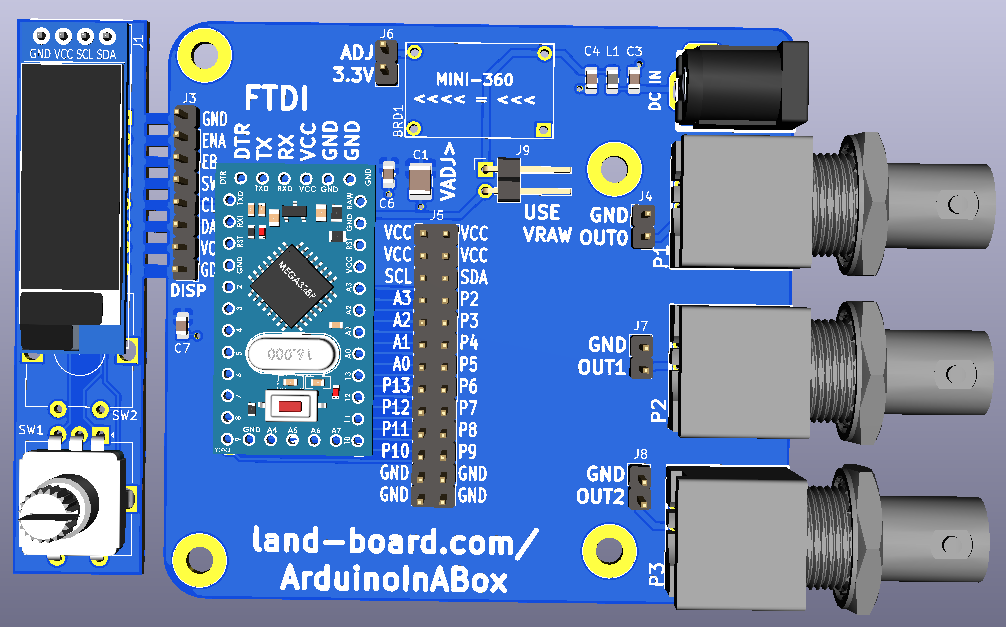
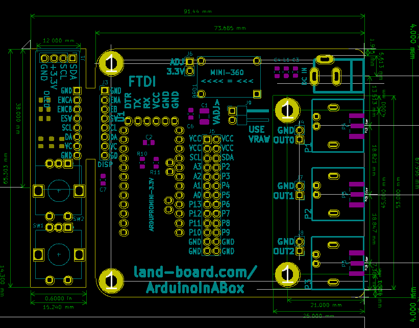
- 3.3 or 5V Arduino Pro Mini
- Arduino pins brought to 2x13 header
- P2-P13, A0-A3
- A4/A5 or SDA/SCL
- Detachable HID
- OLED
- Rotary Encoder
- Leave attached until installing in box
- 3 BNC/SMA connectors
- Brought to headers
- Wide input voltage range
- RF filters on OLED and into board
- Mini360 Switching Mode Power Supply
- Mounts in a standard box
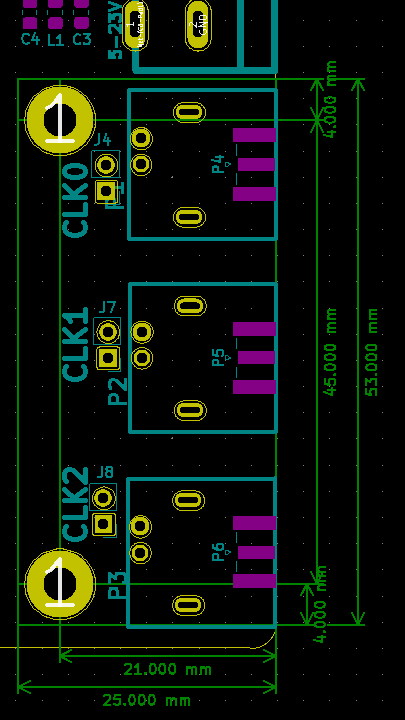
I/O Card
- Connectors are placed on 0.1" grid
- 26 pin, 3 BNC/SMA connectors
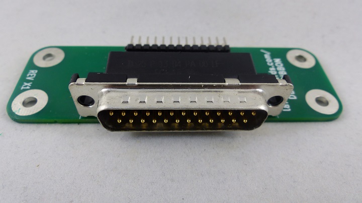
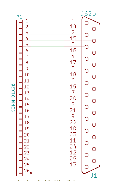
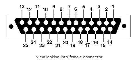
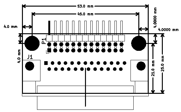
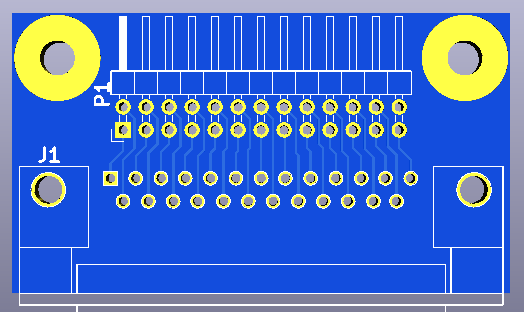
DB-25 Example
- Standard DB-25 female
- Similar to (but narrower and female)
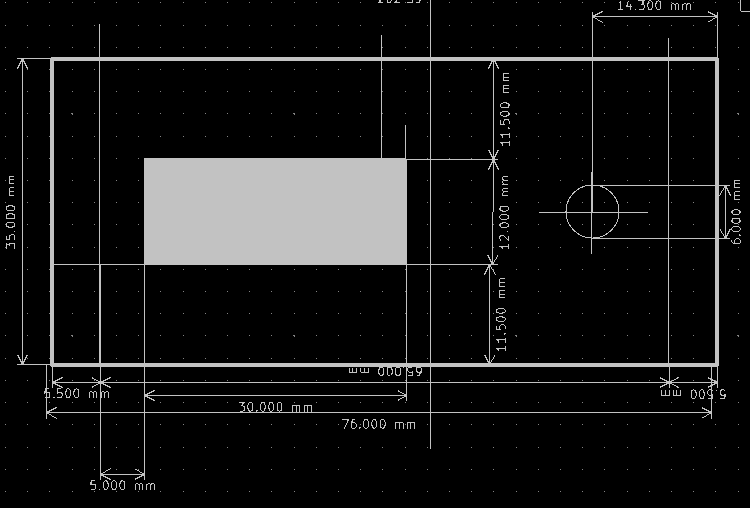
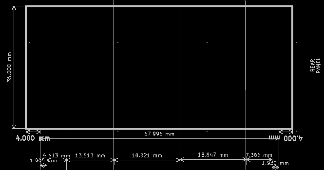
Mechanicals/Enclosure
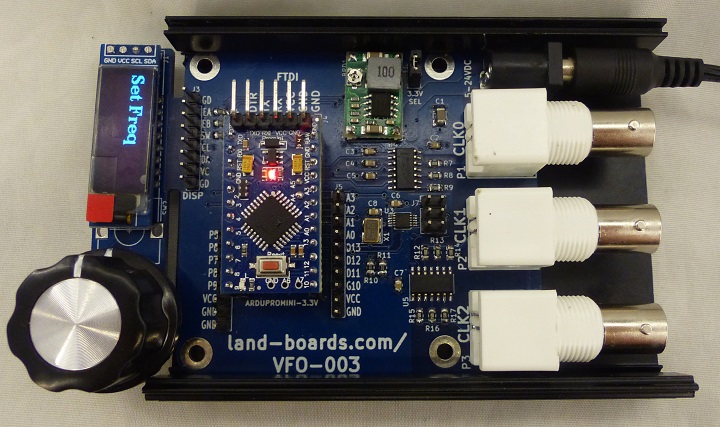
- Board is designed to fit into Aluminum Project Box Enclosure DIY 100*76*35mm - ebay search
- VFO-003 - Similar in a box
