Difference between revisions of "Beaks Through Hole Peaks"
Jump to navigation
Jump to search
Blwikiadmin (talk | contribs) |
Blwikiadmin (talk | contribs) |
||
| Line 132: | Line 132: | ||
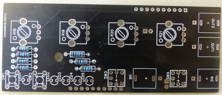
[[file:MI_Beaks_Controls_Resistors-Added_P1080720-720px.jpg]] | [[file:MI_Beaks_Controls_Resistors-Added_P1080720-720px.jpg]] | ||
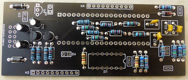
| − | * Analog Front side card with resistors and some caps | + | * Analog Front side card with resistors, transistors, and some caps |
[[file:MI_Beaks_Analog_Card_Front_Side_Resistors_Some_Caps_P1080717-720px.jpg]] | [[file:MI_Beaks_Analog_Card_Front_Side_Resistors_Some_Caps_P1080717-720px.jpg]] | ||
Revision as of 15:29, 14 November 2022
- Through hole version of Mutable Instruments Peaks module
- Beaks Through-hole on Tindie
- Kristian Blåsol's GitHub
- Mathias Levy's Github
Contents
Features
- Acts as
- ADSR
- LFO
- Tap LFO
- Drum
- 4 step Sequencer
- Trigger Delay
- Trigger Randomizer
- Drum Synth
- Buttons
- (2) Manual Triggers - lighted buttons
- Inputs
- (2) Trigger
- Outputs
- 2 PWM Outputs
- Knobs
- Parameters - mode dependent
- Mode controls knob function
- Split (2 knobs each)
- Twin
- Expert
Original Commercial Product
- Mutable Instruments Peaks page
- A SWISS-ARMY KNIFE FOR PERCUSSIVE PATCHES
- Peaks is a dual-channel module – making it very useful for duophonic patches or for controlling/synthesizing the kick/snare rhythmic backbone of a patch.
- Peaks provides 4 different functions in a small 8-HP package: ADSR, LFO / Tap tempo LFO, and drum synth.
- Their common point?
- They are all about generating an audio or CV signal in response to a trigger, and are all focused on rhythmic works.
- 8 HP
- 25mm depth
- +12V@60 mA, -12V@2mA
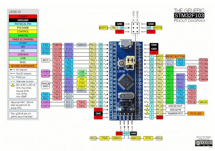
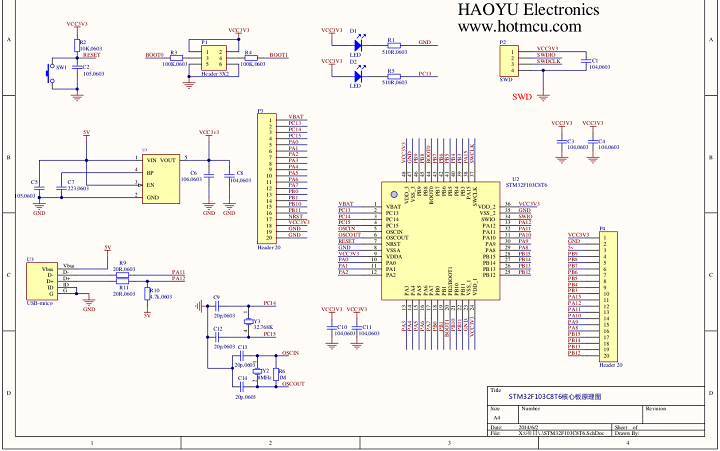
STM32 "Blue Pill"
- "Blue Pill" Pins
- "Blue Pill" Schematic
Videos
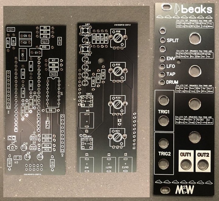
Build PCB Pictures
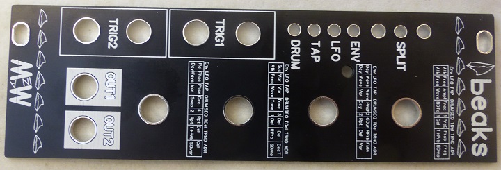
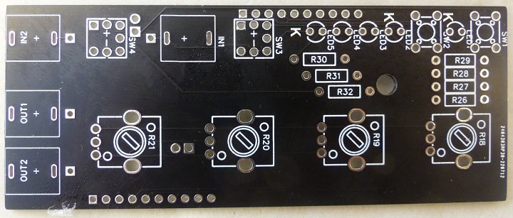
- Front Panel - Front view
- Controls Card - Front view
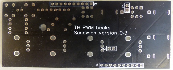
- Controls Card - Rear view
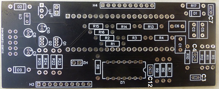
- Processing Card - Front view
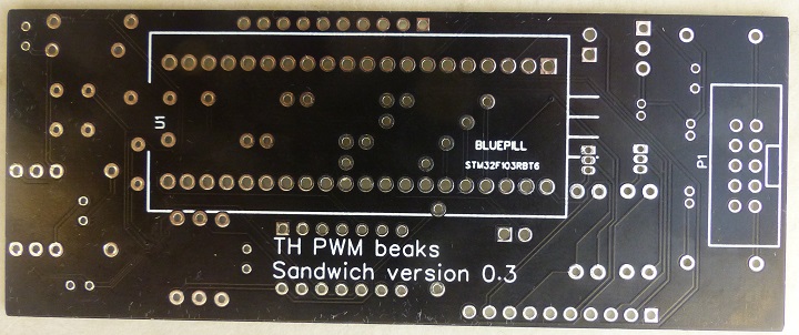
- Processing Card - Rear view
Build Notes
- Get the PCB set with panel and both PCBs for 9$ at Kristian's Tindie store
- Tindie store
- (Or) Download the Gerber files - sound-force page
- Front panel gerber by MyModularJourney
- Braids illustrated. all the waveforms explained
- Discord where you find the mi-th-braids channel and much more
- Gilet / Mutable Instruments Github for all her modules - SMT version
- Modular in a Week playlist
- Support Kristian's work on Patreon
- Kristian's Discord server - See mt-th-braids channel
Parts List Notes
- Parts List has JLCPCB part numbers
- SW1, SW2 - JLCPCB C620311 - Tactile Switch, 6mm, 14mm
- SW3, SW4 - JLCPCB C501573 - Illuminated switch (ordered along with PCB]
- LEDs have Green body when off, but light up in yellow when illuminated
- Can use 100K pots?
- The pots are used to set levels into the STM32 analog pins
- 5pcs Red Common Cathode 7 segment display - MAKE SURE TO CHOOSE COMMON CATHODE
- Get a STM32 Programmer here
- The STM32F103C8T6 is the 64kb version and thus too small but SOMETIMES they are 128kb
- STM32F013CBT8 (128kb version) on ebay... not that many to choose from :/
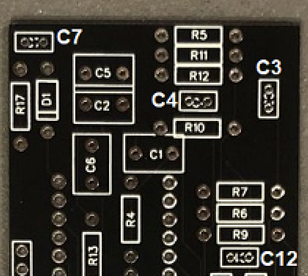
- Added cap ref des C3, C4, C7, C12
- LEDs go Kathode down
Build Pictures
- Controls card with resistors
- Analog Front side card with resistors, transistors, and some caps
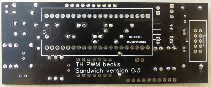
- Analog Rear side card with resistors
