Eurorack ADSR Module
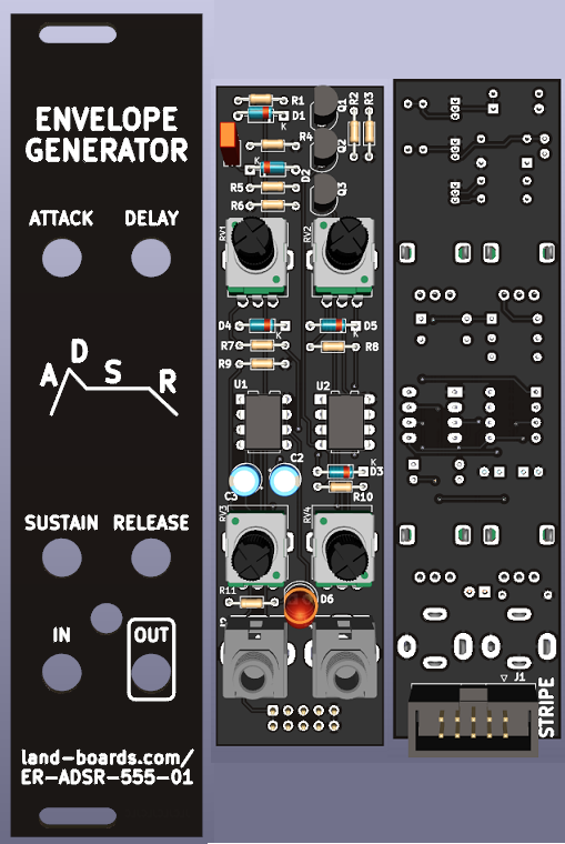
Features
- Attack-DeCay-Sustain-Release Eurorack ADSR Module
- Takes in Gate signal, generates CV to VCA
- Attack, decay, and release pots control speed
- Attack, decay, and release times can range from 200ms to 16s
- Sustain pot sets the sustain voltage level
- LED dims to level
- 3U tall, 6 HP wide
- 555 Based design
- Benjie Jiao MiniADSR
- Original was based on Barry Klein design
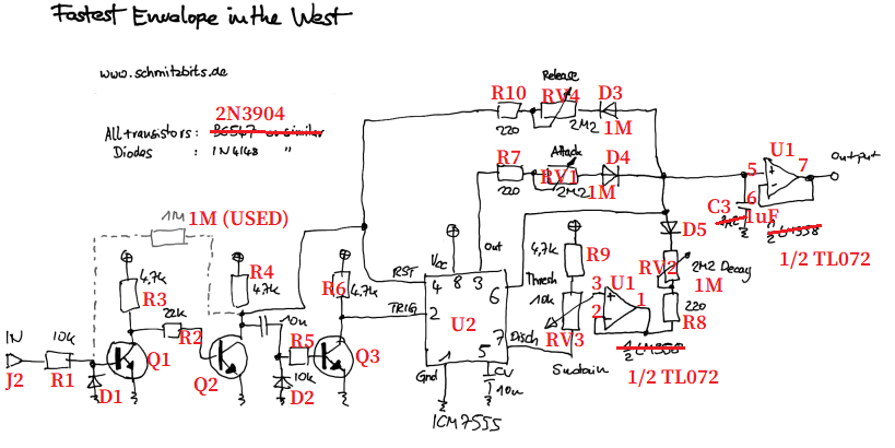
- As built by schmitzbits design - "The Fastest Envelope in the West"
- Benji's build has a three card stack-up and is 4 HP wide
- This card is wider but uses 2 cards
Rev 1 Checkout
- Ordered wrong (earlier) version of the board
- Re-create ordered board in Rev 1 folder
- Annotated schematic
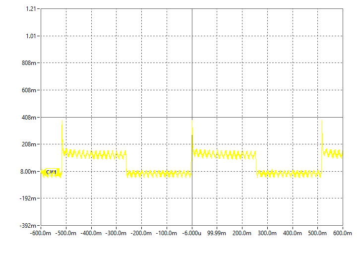
- Drive with Erica Synths EDU Sequencer
- GATE Out output
- At slowest speed, ~2Hz
- My schematic symbols are Schottky but installed 1N4148 like schmitzbits schemati
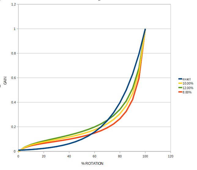
- Using 1 M linear pots instead of 2.2M log pots
- A, D, R pots should have been log pots
- Controls are are "touchy"
- Sustain pot is linear as it should be and "works" but is backwards
- All of the pots are backwards
- A, D, S pots should be CCW for no delay
- ADR series resistors are 220 Ohms but should be 100 Ohms per schmitzbits note
- C3 is 4.7 uF
- Log pot curves
- Does not have 1M that is dashed line on schmitzbits schemati
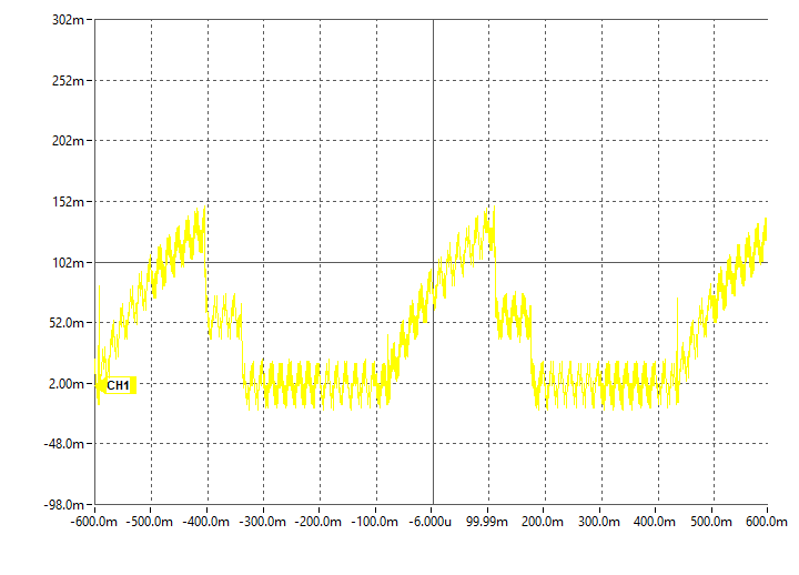
- ADSR controls
- A pot full CW
- D pot full CW
- S Pot mid
- R pot full CW
- Back off Attack just a tiny bit from CCW
- Rounds over the attack like it should but it is very "touchy"
Benjie Jiao - DIY Modular Video
Issues
Rev 1 Issues
- Silkscreen has "DELAY" should be "DECAY"
- A, D, S, R pots are all backwards
- A, D, R pots should be A1M
- Made 2nd card
Cuts
- Cuts before assembling parts on card
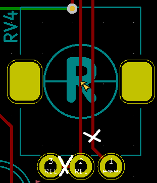
- Cuts to RV1 (pins 2-3)
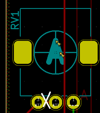
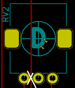
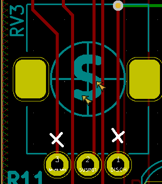
- Cuts to RV4 (pins 2-3 and pin 1)
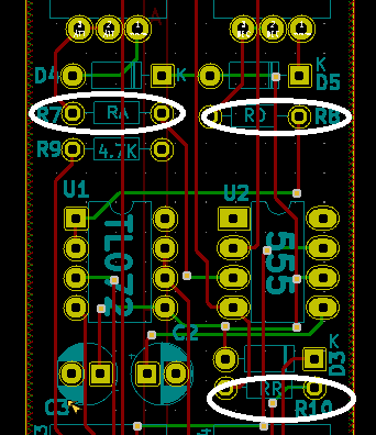
Change Pot Series Resistor Values
- 220 Ohms on A, D, R pots s/b 100 Ohms
- Change R7 to 100 Ohms (A pot)
- Change R8 to 100 Ohms (D pot)
- Change R10 to 100 Ohms (R pot)
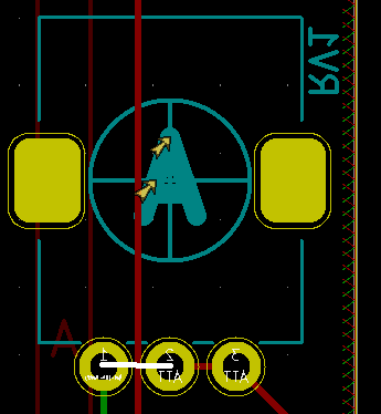
Add wires
- Add wire RV1-2 to RV1-1 (back side view)
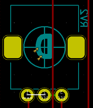
- Add wire RV2-2 to RV2-1 (back side view)
- Add wire R9 left side to Sustain pot, RV3-1
- Add wire U2-7 to Sustain pot, RV3-3
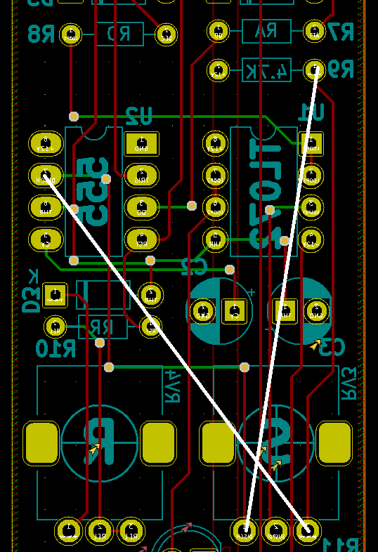
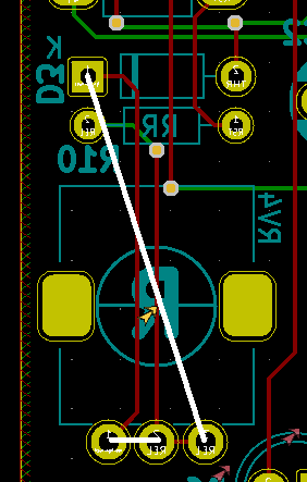
- Add wire D3-K to RV4-3 (back side view)
- Add wire RV4-1 to RV4-2 (back side view)
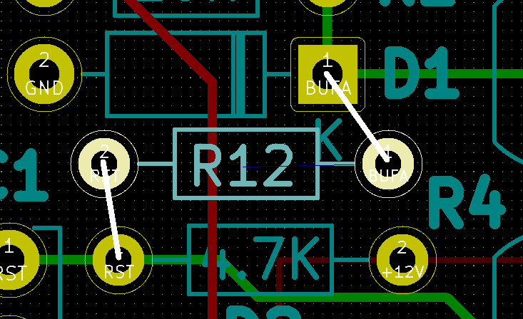
Add Release Resistor
Assembly Sheet
ER-ADSR-555-01 Rev 1 Assembly Sheet


