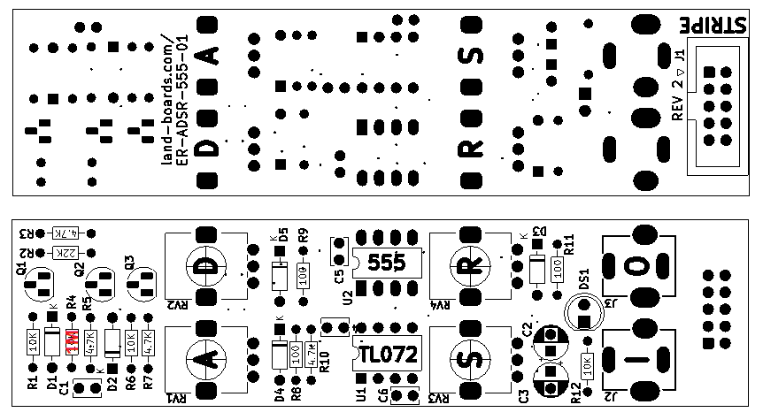
Difference between revisions of "ER-ADSR-555-01 Rev 2 Assembly Sheet"
Jump to navigation
Jump to search
Blwikiadmin (talk | contribs) |
Blwikiadmin (talk | contribs) |
||
| (8 intermediate revisions by the same user not shown) | |||
| Line 2: | Line 2: | ||
== Parts List == | == Parts List == | ||
| + | |||
| + | * [http://land-boards.com/ER-ADSR-555-01/ER-ADSR-555-01_REV3_ibom.html ER-ADSR-555-01 Rev 2 Interactive BOM] | ||
{| class="wikitable" | {| class="wikitable" | ||
| Line 15: | Line 17: | ||
|- | |- | ||
| 1 | | 1 | ||
| − | | | + | | 3 |
| − | | R1 | + | | R1, R6, R12 |
| 10K | | 10K | ||
| | | | ||
| 11 | | 11 | ||
| − | | | + | | 3 |
| − | | | + | | Q1-Q3 |
| − | | | + | | [https://www.onsemi.com/pub/Collateral/2N3903-D.PDF 2N3904] |
|- | |- | ||
| 2 | | 2 | ||
| Line 28: | Line 30: | ||
| R2 | | R2 | ||
| 22K | | 22K | ||
| + | | | ||
| + | | 11 | ||
| + | | 1 | ||
| + | | DS1 | ||
| + | | LED, 5MM | ||
| + | |- | ||
| + | | 3 | ||
| + | | 4 | ||
| + | | R3, R5, R7, R10 | ||
| + | | 4.7K | ||
| | | | ||
| 12 | | 12 | ||
| Line 34: | Line 46: | ||
| A1M | | A1M | ||
|- | |- | ||
| − | |||
| 4 | | 4 | ||
| − | | | + | | 1 |
| − | | | + | | R4 |
| + | | 1M | ||
| | | | ||
| 13 | | 13 | ||
| Line 44: | Line 56: | ||
| B10K | | B10K | ||
|- | |- | ||
| − | | | + | | 5 |
| 3 | | 3 | ||
| R8, R9, R11 | | R8, R9, R11 | ||
| Line 54: | Line 66: | ||
| [https://store.synthrotek.com/TL072P-Op-Amp_p_418.html TL072] | | [https://store.synthrotek.com/TL072P-Op-Amp_p_418.html TL072] | ||
|- | |- | ||
| − | | | + | | 6 |
| 5 | | 5 | ||
| D1-D5 | | D1-D5 | ||
| Line 64: | Line 76: | ||
| LM555N | | LM555N | ||
|- | |- | ||
| − | | | + | | 7 |
| 1 | | 1 | ||
| C1 | | C1 | ||
| Line 74: | Line 86: | ||
| [https://store.synthrotek.com/10-Pin_Keyed_Shrouded_Eurorack_Power_Header Conn_02x05] | | [https://store.synthrotek.com/10-Pin_Keyed_Shrouded_Eurorack_Power_Header Conn_02x05] | ||
|- | |- | ||
| − | | | + | | 8 |
| 1 | | 1 | ||
| C2 | | C2 | ||
| Line 84: | Line 96: | ||
| [https://www.taydaelectronics.com/pj-301bm-3-5-mm-mono-phone-jack.html PJ-301BM] | | [https://www.taydaelectronics.com/pj-301bm-3-5-mm-mono-phone-jack.html PJ-301BM] | ||
|- | |- | ||
| − | | | + | | 9 |
| 1 | | 1 | ||
| C3 | | C3 | ||
| Line 94: | Line 106: | ||
| | | | ||
|- | |- | ||
| − | | | + | | 10 |
| 3 | | 3 | ||
| C4-C6 | | C4-C6 | ||
| 0.1uF | | 0.1uF | ||
| − | |||
| − | |||
| − | |||
| − | |||
| − | |||
| − | |||
| − | |||
| − | |||
| − | |||
| − | |||
| | | | ||
| | | | ||
| Line 115: | Line 117: | ||
|- | |- | ||
|} | |} | ||
| + | |||
| + | == Notes == | ||
| + | |||
| + | === Master Timing Cap === | ||
| + | |||
| + | * Installed C2 (10uF) in machined contact pins | ||
| + | |||
| + | [[file:ER-ADSR-555-01_P1090087-720px.jpg]] | ||
| + | |||
| + | === Decay Fix === | ||
| + | |||
| + | * [[ER-ADSR-555-01#Decay_Fix|Decay fix details]] | ||
| + | * 3.3K Resistor on rear of card | ||
| + | ** Could be installed on top of card into the same holes and vertical | ||
| + | |||
| + | [[file:ER-ADSR-555-01_P1090084-720pxV.jpg]] | ||
Latest revision as of 14:03, 14 March 2023
Parts List
| Find | Qty | Ref Des | Part Number | Find | Qty | Ref Des | Part Number | |
|---|---|---|---|---|---|---|---|---|
| 1 | 3 | R1, R6, R12 | 10K | 11 | 3 | Q1-Q3 | 2N3904 | |
| 2 | 1 | R2 | 22K | 11 | 1 | DS1 | LED, 5MM | |
| 3 | 4 | R3, R5, R7, R10 | 4.7K | 12 | 3 | RV1, RV2, RV4 | A1M | |
| 4 | 1 | R4 | 1M | 13 | 1 | RV3 | B10K | |
| 5 | 3 | R8, R9, R11 | 100 | 14 | 1 | U1 | TL072 | |
| 6 | 5 | D1-D5 | 1N4148 | 15 | 1 | U2 | LM555N | |
| 7 | 1 | C1 | 10nF | 16 | 1 | J1 | Conn_02x05 | |
| 8 | 1 | C2 | 10uF | 17 | 2 | J2, J3 | PJ-301BM | |
| 9 | 1 | C3 | 1uF | |||||
| 10 | 3 | C4-C6 | 0.1uF |
Notes
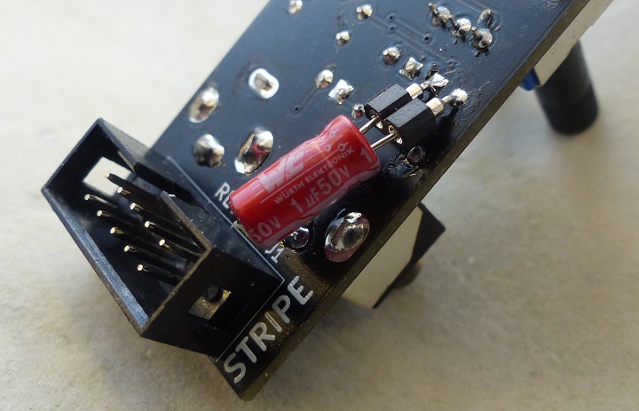
Master Timing Cap
- Installed C2 (10uF) in machined contact pins
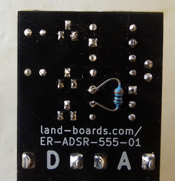
Decay Fix
- Decay fix details
- 3.3K Resistor on rear of card
- Could be installed on top of card into the same holes and vertical


