Difference between revisions of "ER-GATE-SEQ-01"
Jump to navigation
Jump to search
Blwikiadmin (talk | contribs) |
Blwikiadmin (talk | contribs) |
||
| (9 intermediate revisions by the same user not shown) | |||
| Line 1: | Line 1: | ||
| + | [[File:tindie-mediums.png|link=https://www.tindie.com/products/28896/]] | ||
| + | |||
| + | [[file:ER-GATE-SEQ-01_P1080960-720px.jpg]] | ||
| + | |||
== Features == | == Features == | ||
| Line 31: | Line 35: | ||
** R: Reset (lower left, bottom row) | ** R: Reset (lower left, bottom row) | ||
*** Press the button to return the playback step of all channels to the first step | *** Press the button to return the playback step of all channels to the first step | ||
| + | |||
| + | == Build on ER-PROTO-02 Card == | ||
| + | |||
| + | * [[ER-PROTO-02]] | ||
| + | |||
| + | [[file:ER-GATE-SEQ-01_P1080964-720px.jpg]] | ||
| + | |||
| + | === Front Panel === | ||
| + | |||
| + | * OLED mounts over RV1-RV4 | ||
| + | * Cut bigger hole for OLED connector | ||
| + | |||
| + | [[file:ER-GATE-SEQ-01_P1080968-720pxV.jpg]] | ||
| + | |||
| + | === Controls card === | ||
| + | |||
| + | [[file:ER-GATE-SEQ-01_P1080964_ctrls-720px.jpg]] | ||
| + | |||
| + | * J1-J6 are OUT1-OUT6 | ||
| + | * Series output resistors for jacks on card | ||
| + | * RV6 is Rotary Encoder | ||
| + | * RV4 has Rotary Encoder switch contacts | ||
| + | * Cut out at RV5 for GATE IN on Controls card | ||
| + | |||
| + | [[FILE:ER-PROTO-02-ER-GATE-SEQ-01_CTLS_FRONT_CAD.PNG]] | ||
| + | |||
| + | * Jacks connections | ||
| + | |||
| + | [[FILE:ER-PROTO-02-ER-GATE-SEQ-01_SCHEM_J1-7.PNG]] | ||
| + | |||
| + | * Pots connections | ||
| + | |||
| + | [[FILE:ER-PROTO-02-ER-GATE-SEQ-01_SCHEM_J8.PNG]] | ||
| + | |||
| + | === Logic card === | ||
| + | |||
| + | [[file:ER-GATE-SEQ-01_P1080966-720px.jpg]] | ||
| + | |||
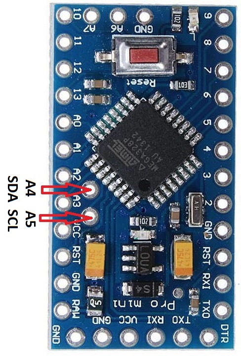
| + | * [[Arduino Pro Mini]] - with ATMega328 | ||
| + | * Pass SDA/SCL to bottom (1x4 right angle header on bottom) | ||
| + | ** SDA/SCL are right angle header on Pro Mini | ||
| + | |||
| + | ==== Daughtercard Prototyping Area ==== | ||
| + | |||
| + | [[FILE:ER-PROTO-02-DB_REAR_PWR.png]] | ||
| + | |||
| + | ==== Circuits ==== | ||
| + | |||
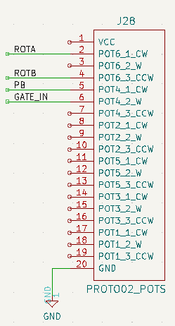
| + | * Rotary Encoder / Switch connections | ||
| + | |||
| + | [[file:ER-PROTO-02-ER-GATE-SEQ-01_SCHEM_J28.PNG]] | ||
| + | |||
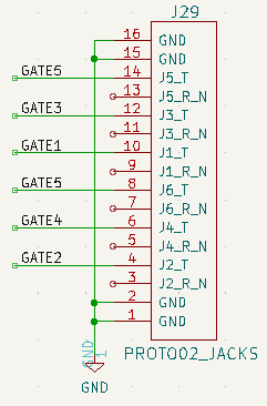
| + | * Jacks connections | ||
| + | |||
| + | [[file:ER-PROTO-02-ER-GATE-SEQ-01_SCHEM_J29.PNG]] | ||
| + | |||
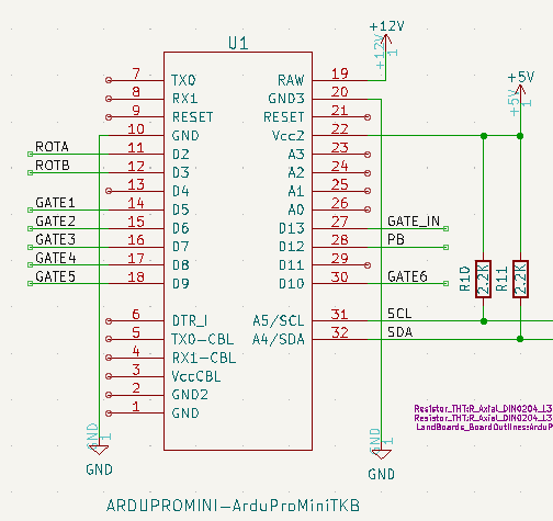
| + | * Arduino | ||
| + | |||
| + | [[file:ER-PROTO-02-ER-GATE-SEQ-01_SCHEM_U1.PNG]] | ||
| + | |||
| + | [[file:2014-05-14T23_52_48.894Z-3-720px.jpg]] | ||
| + | |||
| + | [[file:ER-PROTO-02-ER-GATE-SEQ-01_SCHEM_SCH_DIODES.PNG]] | ||
| + | |||
| + | * OLED | ||
| + | |||
| + | [[file:ER-PROTO-02-ER-GATE-SEQ-01_SCHEM_OLED.PNG]] | ||
== Prototype Build == | == Prototype Build == | ||
| Line 73: | Line 144: | ||
== Software == | == Software == | ||
| + | * [https://github.com/land-boards/lb-Arduino-Code/blob/master/LBCards/SYNTHS/ER-GATE-SEQ-01/ER_GATE_SEQ_TEST_V1/ER_GATE_SEQ_TEST_V1.ino ER_GATE_SEQ_TEST_V1.ino] - Hardware test code | ||
| + | ** Test all 6 GATE outputs | ||
| + | ** Use CLK_IN as an OUT for this test only | ||
* [https://github.com/land-boards/lb-Arduino-Code/blob/master/LBCards/SYNTHS/ER-GATE-SEQ-01/ER_EUC_SEQ_V1/ER_EUC_SEQ_V1.ino ER_EUC_SEQ_V1.ino] | * [https://github.com/land-boards/lb-Arduino-Code/blob/master/LBCards/SYNTHS/ER-GATE-SEQ-01/ER_EUC_SEQ_V1/ER_EUC_SEQ_V1.ino ER_EUC_SEQ_V1.ino] | ||
| + | ** [https://note.com/solder_state/n/n17c69afd484d Euclidean rhythm sequencer] - HAGIWO build | ||
| + | * [https://note.com/solder_state/n/n17c69afd484d 6CH Trigger Sequencer] - HAGIWO previous version | ||
Latest revision as of 11:55, 7 January 2023
Contents
Features
- GATE Sequencer
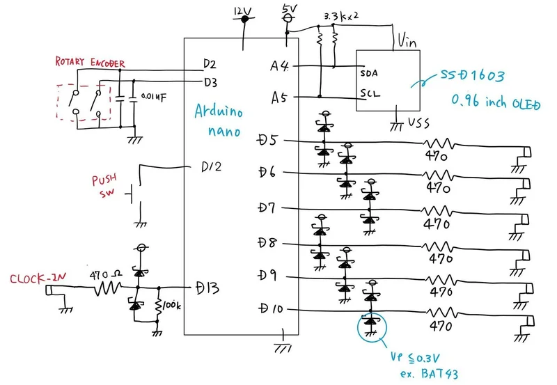
- Based on HAGIWO Euclidean rhythm sequencer
- OLED Display: 128*64 size
- Rotary Encoder: Parameter Selection
- PUSH Button: Parameter Change/Determination
- Trigger Output: 6CH (0-5V) Trigger Input: 1CH (0-5V)
HAGIWO Design
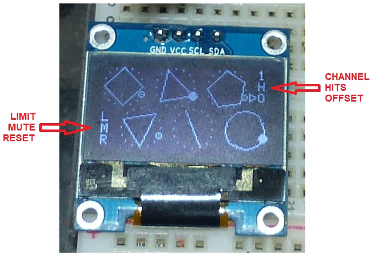
HAGIWO Menu System
- Rotary Encoder: Parameter Selection
- PUSH Button: Parameter Change/Determination
- 6 Parameters - Arrow points to current channel/option
- 1-6, R: Select channel 1-6 (upper right, top row), Random
- H: Hits (Upper right, middle row) - Number of points
- Number of outputs out of 16 steps
- O: Offset (Upper right, bottom row)
- Shift the start of the rhythm by offsetting LIMIT
- Return to the first step when there is a trigger input for the number of times the set value is set
- For example, if you set it to 5, it will return to the first step after outputting 1~5 steps. It can be used in a polyrhythmic way
- L: Limit (lower left, top row) - number of steps
- M: Mute channel (lower left, middle row)
- Eliminates the trigger output of the selected CH.
- R: Reset (lower left, bottom row)
- Press the button to return the playback step of all channels to the first step
Build on ER-PROTO-02 Card
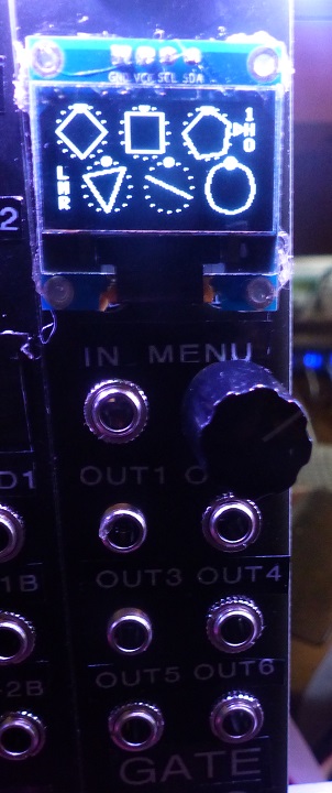
Front Panel
- OLED mounts over RV1-RV4
- Cut bigger hole for OLED connector
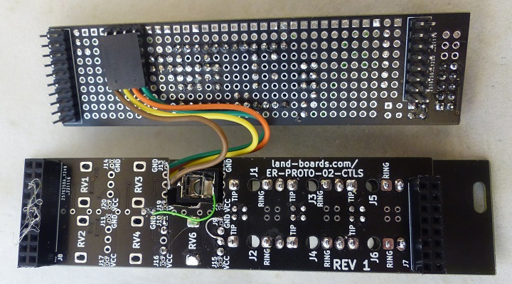
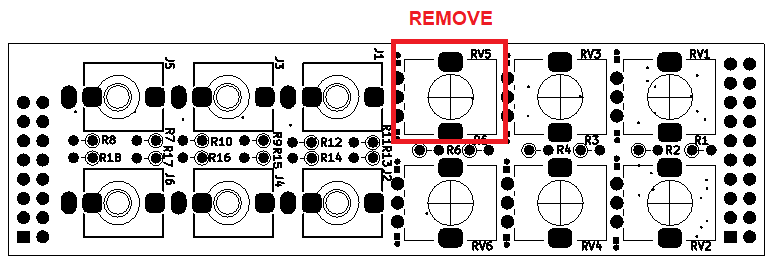
Controls card
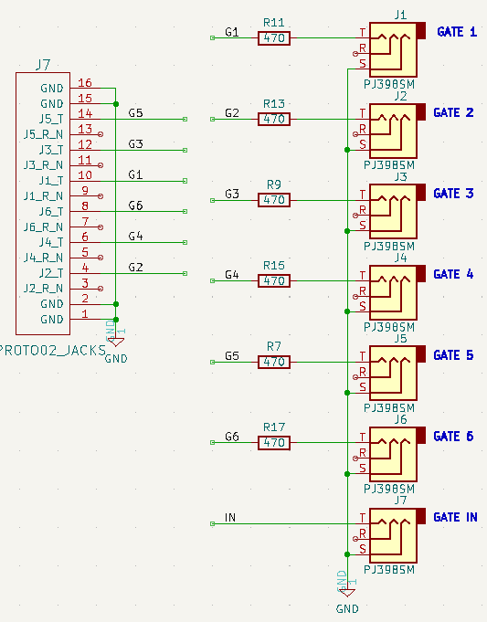
- J1-J6 are OUT1-OUT6
- Series output resistors for jacks on card
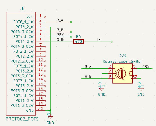
- RV6 is Rotary Encoder
- RV4 has Rotary Encoder switch contacts
- Cut out at RV5 for GATE IN on Controls card
- Jacks connections
- Pots connections
Logic card
- Arduino Pro Mini - with ATMega328
- Pass SDA/SCL to bottom (1x4 right angle header on bottom)
- SDA/SCL are right angle header on Pro Mini
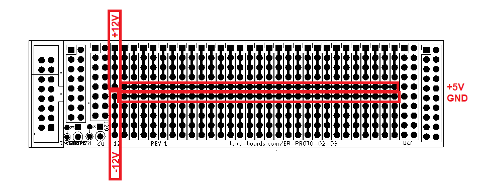
Daughtercard Prototyping Area
Circuits
- Rotary Encoder / Switch connections
- Jacks connections
- Arduino
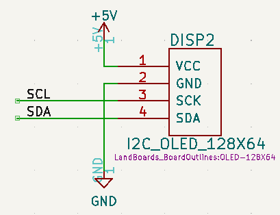
- OLED
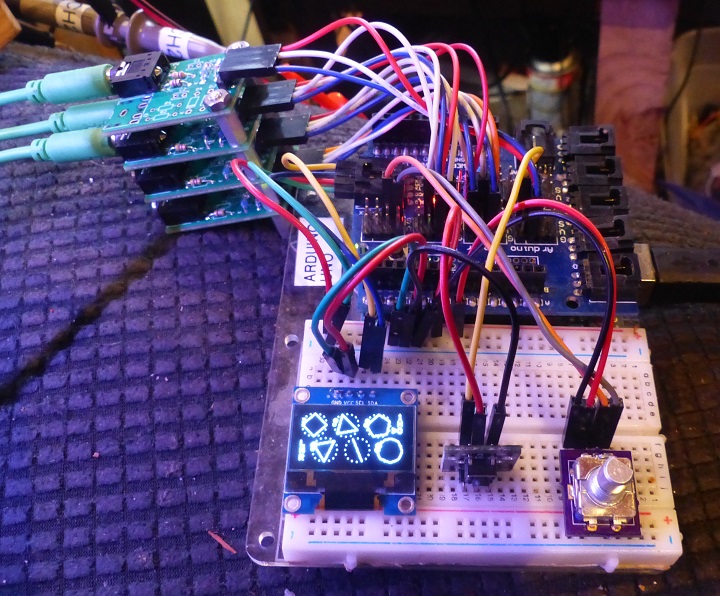
Prototype Build
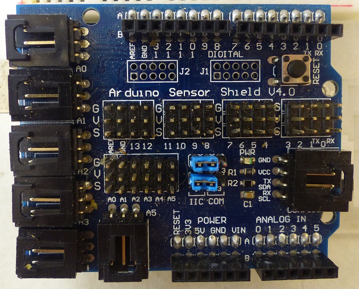
Arduino Sensor Shield
- Arduino UNO
- Arduino Sensor Shield
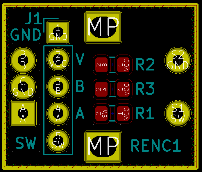
Rotary Encoder
- Rotary Encoder
- Pinout
- G
- V
- B
- A
- Switch
- Viewed from bottom
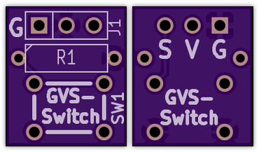
GVS Switch
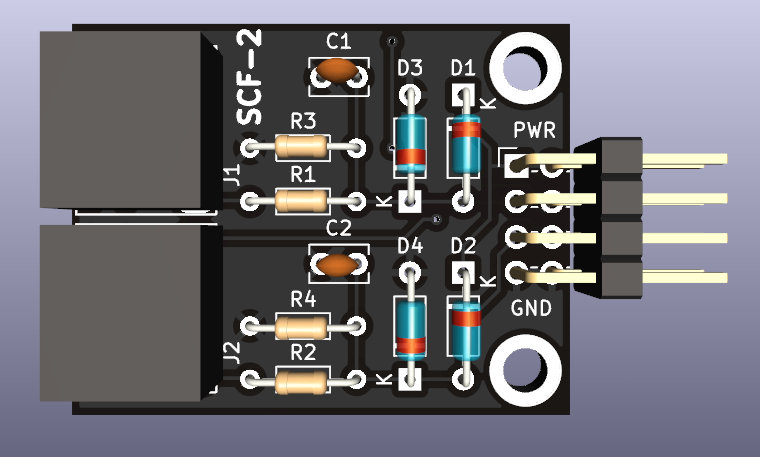
SCF-2 - Jacks
- SCF-2 - Jacks
- One card populated with 1 3.5mm jack
- 3 cards populated with 2 jacks
Software
- ER_GATE_SEQ_TEST_V1.ino - Hardware test code
- Test all 6 GATE outputs
- Use CLK_IN as an OUT for this test only
- ER_EUC_SEQ_V1.ino
- Euclidean rhythm sequencer - HAGIWO build
- 6CH Trigger Sequencer - HAGIWO previous version


