Difference between revisions of "ER-MIDI-CV4-02"
Jump to navigation
Jump to search
Blwikiadmin (talk | contribs) (→Rev 2) |
Blwikiadmin (talk | contribs) |
||
| (42 intermediate revisions by the same user not shown) | |||
| Line 1: | Line 1: | ||
| + | [[File:tindie-mediums.png|link=https://www.tindie.com/products/28969/]] | ||
| + | |||
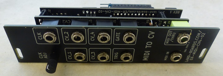
[[FILE:ER-MIDI-CV4-02_P1080867-720px.jpg]] | [[FILE:ER-MIDI-CV4-02_P1080867-720px.jpg]] | ||
| Line 10: | Line 12: | ||
** Processor card | ** Processor card | ||
* [[Arduino_Pro_Mini|Arduino Pro Mini]] | * [[Arduino_Pro_Mini|Arduino Pro Mini]] | ||
| + | ** Either ATMega168 or ATMega328 | ||
** 16 MHz | ** 16 MHz | ||
** 5V | ** 5V | ||
| + | ** Programmed via Serial | ||
* MIDI In | * MIDI In | ||
** TRS Type A jack MIDI In | ** TRS Type A jack MIDI In | ||
** USB MIDI In if external FTDI card/cable | ** USB MIDI In if external FTDI card/cable | ||
* (4) 0-4.096V Analog CV outs | * (4) 0-4.096V Analog CV outs | ||
| + | ** 4 octaves | ||
** [https://www.mouser.com/ProductDetail/Microchip-Technology-Atmel/MCP4822-E-P?qs=sGAEpiMZZMtgJDuTUz7Xu5a0A%252BlHhkxt3QSpqvc4zyk%3D MCP4822 12-bit D/A] - SPI Interface | ** [https://www.mouser.com/ProductDetail/Microchip-Technology-Atmel/MCP4822-E-P?qs=sGAEpiMZZMtgJDuTUz7Xu5a0A%252BlHhkxt3QSpqvc4zyk%3D MCP4822 12-bit D/A] - SPI Interface | ||
*** [https://www.mouser.com/datasheet/2/268/21953a-8929.pdf MCP4822 Datasheet] | *** [https://www.mouser.com/datasheet/2/268/21953a-8929.pdf MCP4822 Datasheet] | ||
| Line 23: | Line 28: | ||
* CLK output (0-5V) | * CLK output (0-5V) | ||
* TRIG output (0-5V) | * TRIG output (0-5V) | ||
| − | * Standard Eurorack | + | * Standard Eurorack 10 pin power header |
=== Credits === | === Credits === | ||
| Line 180: | Line 185: | ||
* MIDI Input | * MIDI Input | ||
* TRS Type A | * TRS Type A | ||
| + | |||
| + | [[FILE:ER-MIDI-CV4_J8.PNG]] | ||
| + | |||
| + | ===== MIDI TRS A ===== | ||
| + | |||
| + | * From [https://minimidi.world/ minimidi.world] | ||
| + | * DIN | ||
| + | |||
| + | [[file:MINIMIDI_WORLD_DIN.PNG]] | ||
| + | |||
| + | * TRS A | ||
| + | |||
| + | [[file:MINIMIDI_WORLD_TYPE-A.PNG]] | ||
==== J9 - MIDI Out ==== | ==== J9 - MIDI Out ==== | ||
| Line 194: | Line 212: | ||
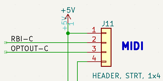
[[FILE:ER-MIDI-CV4-CTLS_J11.PNG]] | [[FILE:ER-MIDI-CV4-CTLS_J11.PNG]] | ||
| − | == Application == | + | == Applications == |
| + | |||
| + | * Card test code | ||
| + | * Basic Application | ||
| + | * Polyphonic/Drum Triggers Application | ||
| + | |||
| + | === Programming === | ||
| − | * | + | * Program with FTDI Serial |
| − | + | * FTDI set to 5V signal levels | |
| − | + | * Cable does not connect VCC | |
| − | * | ||
| − | |||
| − | * | ||
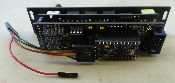
| − | + | [[file:ER-MIDI-CV4-02_P1080860-720px.jpg]] | |
* Unplug MIDI in cable from front panel | * Unplug MIDI in cable from front panel | ||
| Line 210: | Line 231: | ||
* Disconnect FTDI | * Disconnect FTDI | ||
* Connect MIDI in cable to front panel | * Connect MIDI in cable to front panel | ||
| + | |||
=== Card Test Code === | === Card Test Code === | ||
| − | * [https://github.com/land-boards/lb-Arduino-Code/blob/master/LBCards/SYNTHS/ER_MIDI_CV/TestPotDigIOs/TestPotDigIOs.ino TestPotDigIOs] | + | * Code useful to verify card is correctly assembled |
| − | * [https://github.com/land-boards/lb-Arduino-Code/blob/master/LBCards/SYNTHS/ER_MIDI_CV/ER_MIDI_CV4_04_TEST_DACs/ER_MIDI_CV4_04_TEST_DACs.ino ER_MIDI_CV4_04_TEST_DACs] | + | * [https://github.com/land-boards/lb-Arduino-Code/blob/master/LBCards/SYNTHS/ER_MIDI_CV/TestPotDigIOs/TestPotDigIOs.ino TestPotDigIOs] |
| + | ** Test Digital Outputs (CLK, TRIG, GATE) and Speed Pot | ||
| + | * [https://github.com/land-boards/lb-Arduino-Code/blob/master/LBCards/SYNTHS/ER_MIDI_CV/ER_MIDI_CV4_04_TEST_DACs/ER_MIDI_CV4_04_TEST_DACs.ino ER_MIDI_CV4_04_TEST_DACs] | ||
| + | ** Read pot, scale value. write to 4 analog outputs | ||
| + | ** Also, drive CLK, TRIG, GATE digital outputs | ||
=== HAGIWO code baseline === | === HAGIWO code baseline === | ||
| Line 221: | Line 247: | ||
** Used as baseline and converted to CircuitPython | ** Used as baseline and converted to CircuitPython | ||
| − | === | + | === Basic Application=== |
| + | |||
| + | * [https://github.com/land-boards/lb-Arduino-Code/tree/master/LBCards/SYNTHS/ER_MIDI_CV/ER_MIDI_CV4_02 ER_MIDI_CV4_02] - Base application | ||
| + | * Listens on channel 0 | ||
| + | ** CV1 controls pitch | ||
| + | * Ex: Use with [[ER-VCO-03]] to control pitch and Mod | ||
| + | ** CV_1 = V/OCT | ||
| + | ** CV_2 = MOD | ||
| + | * Use GATE output into [[ER-ADSR-555-01]] output of ADSR to MOD input of [[ER-VCA2-01]] to control amplitude | ||
| + | * [http://fortyseveneffects.github.io/arduino_midi_library/ Arduino MIDI Library] | ||
| + | * [https://www.inspiredacoustics.com/en/MIDI_note_numbers_and_center_frequencies MIDI Notes] | ||
| + | |||
| + | === Polyphonic and Drum Triggers Code === | ||
* [https://github.com/land-boards/lb-Arduino-Code/blob/master/LBCards/SYNTHS/ER_MIDI_CV/ER_MIDI_CV4_02/ER_MIDI_CV4_02.ino ER_MIDI_CV4_02] - Working code | * [https://github.com/land-boards/lb-Arduino-Code/blob/master/LBCards/SYNTHS/ER_MIDI_CV/ER_MIDI_CV4_02/ER_MIDI_CV4_02.ino ER_MIDI_CV4_02] - Working code | ||
| − | + | * #define for polyphonic and drum modes | |
| + | ** #define POLYPHONIC uses CV1-4, a single gate output | ||
| + | ** #define DRUM_TRIGGER_OUTS uses TRIG and CLK to trigger drums Beaks (Peaks) | ||
<pre> | <pre> | ||
// V/OCT LSB for DAC | // V/OCT LSB for DAC | ||
| Line 242: | Line 282: | ||
// Table counts up by integer steps - rounded 83.333 mV | // Table counts up by integer steps - rounded 83.333 mV | ||
</pre> | </pre> | ||
| + | |||
| + | === Drum Controller Application === | ||
| + | |||
| + | * Use TRIG and GATE output jacks to drive [[Beaks_Through_Hole_Peaks|Beaks]] in Drum mode | ||
| + | * Re-label Gate as TRIG 2 on Front Panel | ||
| + | * Using USB MIDI as MIDI source | ||
| + | ** [[ER-USB-MIDI]] through [[ER-MIDI-THRU]] into MIDI In on this card | ||
| + | *** Set [[ER-USB-MIDI]] to pass all channels | ||
| + | ** [[ER-MIDI-THRU]] always passes all channels | ||
| + | ** Keyboard off or unplugged from [[ER-MIDI-THRU]] | ||
| + | * Using keyboard as MIDI source | ||
| + | ** Keyboard plugged into [[ER-MIDI-THRU]] | ||
| + | ** [[ER-MIDI-THRU]] not plugged into ER-MIDI-CV4-02 | ||
| + | * Uses 2 ER-MIDI-CV4-02 card sets | ||
| + | ** One ER-MIDI-CV4-02 card set to listen on MIDI Channel 1 | ||
| + | ** Second ER-MIDI-CV4-02 card set to listen to Drums on Channel 10 | ||
| + | * [https://www.midi.org/specifications-old/item/gm-level-1-sound-set GM 1 Sound Set] | ||
| + | |||
| + | ==== Drum Controller Build notes ==== | ||
| + | |||
| + | * Do not populate D/A converter | ||
| + | * Do not populate CV jacks | ||
| + | * Do not populate related discrete parts | ||
== 3D Views == | == 3D Views == | ||
| Line 264: | Line 327: | ||
== Issues == | == Issues == | ||
| + | |||
| + | [[file:ER-MIDI-CV4-02_P1080869-720px.jpg]] | ||
=== Rev 2 === | === Rev 2 === | ||
Latest revision as of 03:36, 10 January 2023
Contents
Features
- Eurorack 6HP, 3U module
- Three card stack-up
- Front Panel card
- Controls card
- 9 Jacks, 1 pot
- Processor card
- Arduino Pro Mini
- Either ATMega168 or ATMega328
- 16 MHz
- 5V
- Programmed via Serial
- MIDI In
- TRS Type A jack MIDI In
- USB MIDI In if external FTDI card/cable
- (4) 0-4.096V Analog CV outs
- 4 octaves
- MCP4822 12-bit D/A - SPI Interface
- D/A has built in output opamps, set gain to 2X
- Outputs may only swing 2x 2.048V or 4.096V (4 octaves)
- GATE output (0-5V)
- CLK output (0-5V)
- TRIG output (0-5V)
- Standard Eurorack 10 pin power header
Credits
- Adapted from HAGIWO's MIDI to CV module
- Translate from Japanese to English using browser
- Has 4 Analog Outputs instead of 2
- Arduino Pro Mini instead of Arduino NANO
- Based also on SYNTH-MIDI-CTL-01
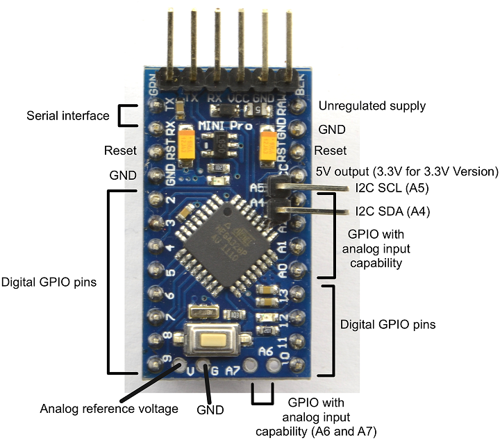
Arduino Pins
- Arduino Pro Mini
- Analog 1 - Speed Adjust POT
- A4 = SDA
- A5 = SCL
- D8 = LDAC1* to CV_1, CV2
- D9 = LDAC2* to CV_3, CV_4
- D13 = SPI CSK to both ADCs
- D11 = SPI MOSI to both ADCs
- D10 = SLAVE SELECT to both ADCs
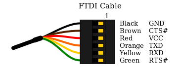
Connection to FTDI
- Use FTDI-49MM card
- Right angle 1x6 pins
- Pinout
- GND
- CTSn (IN)
- VCC
- TX (OUT)
- RX (IN)
- RTSn (OUT)
- Arduino Pro Mini Serial Connector
- Marking matches FTDI cable pinouts/color codes
- BLK
- GND
- VCC
- RX
- TX
- GRN
Connectors
Processing Card Connectors
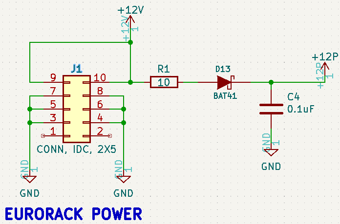
J1 - Eurorack Power
- 2x5 IDC connector
- Only uses +12V (and GND)
- Diode polarity protected, series resistor
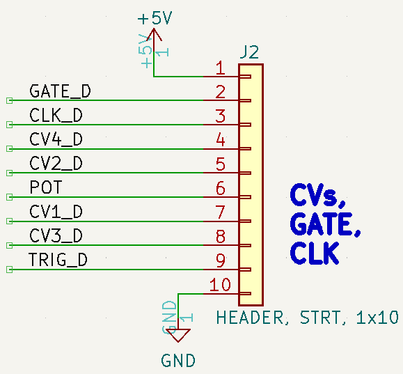
J2 - CVs, GATE, CLK (to/from Controls card)
- J12 on Controls card
- Pinout
- VCC (+5V)
- GATE
- CLK
- CV4
- CV2
- POT
- CV1
- CV3
- TRIGGER
- GND
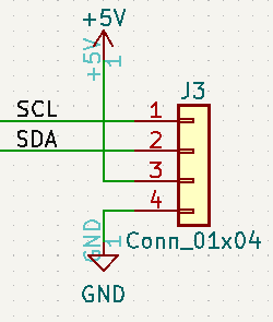
J3 - I2C
- Pinout
- SCL
- SDA
- VCC (+5V)
- GND
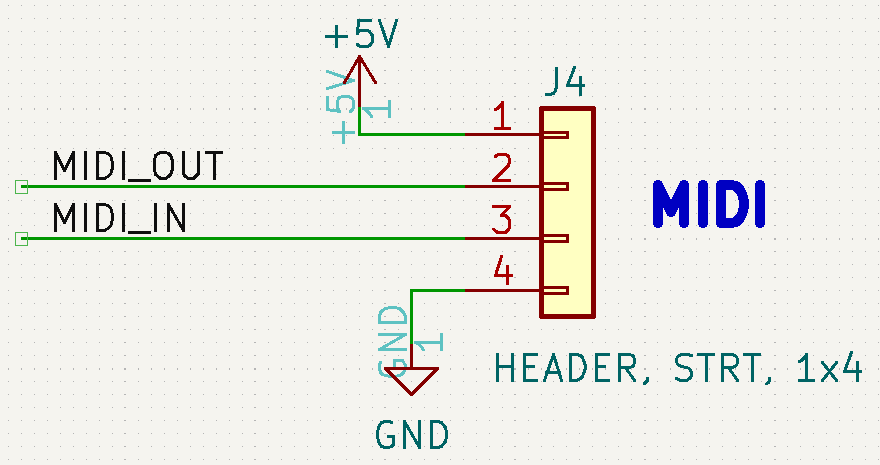
J4 - MIDI (to/from Controls card)
- J9 on Controls card
- Pinout
- VCC (+5V)
- MIDI Out
- MIDI In
- GND
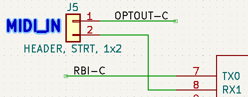
J5 - MIDI into RX
- Remove to use MIDI from Controls card
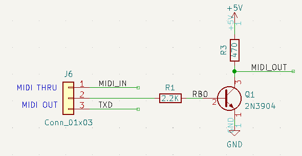
J6 - MIDI OUT/THRU Select
- 1-2 = MIDI Thru
- 2-3 = MIDI out from Arduino TX
Controls Card Connectors
J1 - CLK
- MIDI Clock out
- 0-5V, Digital
J2 - CV1 Out
- Control Voltage out
- 0-5V Analog Clock
J3 - CV2 Out
- Control Voltage out
- 0-5V Analog Clock
J4 - CV3 Out
- Control Voltage out
- 0-5V Analog Clock
J5 - CV4 Out
- Control Voltage out
- 0-5V Analog Clock
J6 - TRIGGER
- MIDI Trigger out
- 0-5V, Digital
J7 - GATE
- MIDI Gate out
- 0-5V, Digital
J8 - MIDI In
- MIDI Input
- TRS Type A
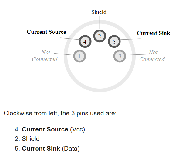
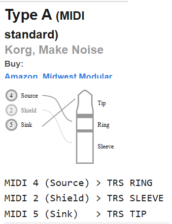
MIDI TRS A
- From minimidi.world
- DIN
- TRS A
J9 - MIDI Out
- MIDI Output
- TRS Type A
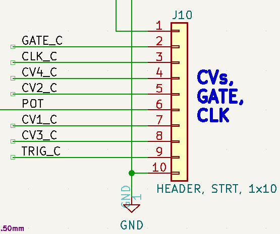
J10 - CVs, GATE, CLK, TRIG
J11 - MIDI
Applications
- Card test code
- Basic Application
- Polyphonic/Drum Triggers Application
Programming
- Program with FTDI Serial
- FTDI set to 5V signal levels
- Cable does not connect VCC
- Unplug MIDI in cable from front panel
- Connect FTDI card with 1:1 cable
- Download code in Arduino IDE
- Disconnect FTDI
- Connect MIDI in cable to front panel
Card Test Code
- Code useful to verify card is correctly assembled
- TestPotDigIOs
- Test Digital Outputs (CLK, TRIG, GATE) and Speed Pot
- ER_MIDI_CV4_04_TEST_DACs
- Read pot, scale value. write to 4 analog outputs
- Also, drive CLK, TRIG, GATE digital outputs
HAGIWO code baseline
- SYNTHMIDICTL01.ino
- Runs on Arduino ATMEGA328 (Arduino NANO or Pro Mini)
- Used as baseline and converted to CircuitPython
Basic Application
- ER_MIDI_CV4_02 - Base application
- Listens on channel 0
- CV1 controls pitch
- Ex: Use with ER-VCO-03 to control pitch and Mod
- CV_1 = V/OCT
- CV_2 = MOD
- Use GATE output into ER-ADSR-555-01 output of ADSR to MOD input of ER-VCA2-01 to control amplitude
- Arduino MIDI Library
- MIDI Notes
Polyphonic and Drum Triggers Code
- ER_MIDI_CV4_02 - Working code
- #define for polyphonic and drum modes
- #define POLYPHONIC uses CV1-4, a single gate output
- #define DRUM_TRIGGER_OUTS uses TRIG and CLK to trigger drums Beaks (Peaks)
// V/OCT LSB for DAC
// ER-VCO-03 characteristics
//  PITCH ADJ knob roughly centered
//  0V = 93.08 Hz (roughly F2)
//  1V = 179 Hz (G3)
//  1.52V = 261 Hz (C4)
//  2V = 365 Hz (G4)
//  3V = 722 Hz (G5)
//  4V = 1.45 KHz (G6)
//  5V = 3.05 KHz (G7)
// Max output voltage of this card is 4.096V (4 octaves)
//  1mV per DAC count
// 12 notes per octave = 1/12V per note = 83.333 mV
// Steps are in 83.333 mV
// Table counts up by integer steps - rounded 83.333 mV
Drum Controller Application
- Use TRIG and GATE output jacks to drive Beaks in Drum mode
- Re-label Gate as TRIG 2 on Front Panel
- Using USB MIDI as MIDI source
- ER-USB-MIDI through ER-MIDI-THRU into MIDI In on this card
- Set ER-USB-MIDI to pass all channels
- ER-MIDI-THRU always passes all channels
- Keyboard off or unplugged from ER-MIDI-THRU
- ER-USB-MIDI through ER-MIDI-THRU into MIDI In on this card
- Using keyboard as MIDI source
- Keyboard plugged into ER-MIDI-THRU
- ER-MIDI-THRU not plugged into ER-MIDI-CV4-02
- Uses 2 ER-MIDI-CV4-02 card sets
- One ER-MIDI-CV4-02 card set to listen on MIDI Channel 1
- Second ER-MIDI-CV4-02 card set to listen to Drums on Channel 10
- GM 1 Sound Set
Drum Controller Build notes
- Do not populate D/A converter
- Do not populate CV jacks
- Do not populate related discrete parts
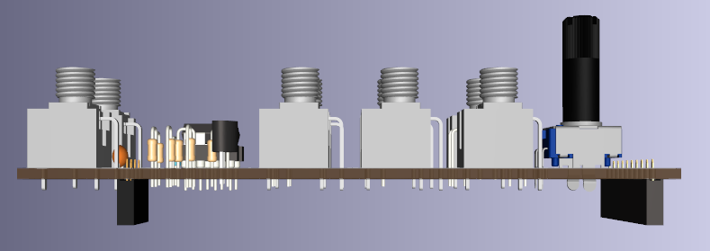
3D Views
- Controls card side view
- Processing card side view
Videos
- HAGIWO MIDI to CV module
- Midi2CV - A utility module for converting MIDI messages to CV] Benjie Jiao - DIY Modular Synth Project_
Issues
Rev 2
- Daughtercard
- Fixed missing connection D14 anode to GND
- Moved R1 down a bit
- Haven't ordered yet (2022-12-04)
Rev 1
- Daughtercard
- Missing connection D14 anode to GND
- Add wire D14-Anode to D9-Anode
- R1 is close to Arduino socket (fit OK, but tight)
- Missing connection D14 anode to GND

