Difference between pages "File:ADE-1.NanoVNA RF-to-IF 8-10MHz.png" and "Kits and Parts Mixers"
(Difference between pages)
Jump to navigation
Jump to search
Blwikiadmin (talk | contribs) |
Blwikiadmin (talk | contribs) |
||
| Line 1: | Line 1: | ||
| + | == Kits and Parts Mixers Features in Common == | ||
| + | * All Ports are 50Ω | ||
| + | * +7dBm Local Oscillator Injection Design | ||
| + | * Full Diplexer at the IF Port | ||
| + | * Optional Attenuators for RF & LO Ports | ||
| + | * Available as bare PCB or kit of parts | ||
| + | |||
| + | === My Typical Applications === | ||
| + | |||
| + | * 7 MHz RF, 40 M band | ||
| + | * 16 MHz LO | ||
| + | ** Si5351A square wave drive, 50 Ohm source impedance, 1.65V peak | ||
| + | * 9 MHz IF feeds Crystal Filter | ||
| + | ** SSB or CW [[Crystal Filter Design|Crystal Filter Design]] | ||
| + | *** [[Crystal Filter Design#SSB 4 Crystal Filter on Kits and Parts Board|SSB4 Crystal filter]] | ||
| + | *** [[Crystal_Filter_Design#CW 5 Crystal Filter on Kits and Parts Board|CW5 Crystal Filter]] | ||
| + | |||
| + | == Kits and Parts ADE-1 Mixer == | ||
| + | |||
| + | * [https://kitsandparts.com/ADE.php Kits and Parts Mixer] | ||
| + | * Build and tune diplexer first | ||
| + | |||
| + | [[file:ADE-1.SCH.png]] | ||
| + | |||
| + | [[file:ADE-1.PCB.png]] | ||
| + | |||
| + | ==== Toroid Winding Direction ==== | ||
| + | |||
| + | * Toroids needs to be wound to match the pad locations/offsets on the PCB | ||
| + | |||
| + | [[file:toroid-cw.jpg]] | ||
| + | |||
| + | === ADE-1 Schematic === | ||
| + | |||
| + | [[file:ADE-1_Schematic.PNG]] | ||
| + | |||
| + | === Performance === | ||
| + | |||
| + | [[file:Chart_dBm-to-Volts.PNG]] | ||
| + | |||
| + | [[file:ADE-1_Performance.PNG]] | ||
| + | |||
| + | [[file:ADE-1_ElectricalSpecs.PNG]] | ||
| + | |||
| + | === Port VWSR === | ||
| + | |||
| + | * Measured VSWR of 2.23 at 9 MHz with NanoVNA matches spec nicely | ||
| + | |||
| + | [[file:ADE-1_LO_VSWR.PNG]] | ||
| + | |||
| + | [[file:ADE-1_IF_VSWR.PNG]] | ||
| + | |||
| + | [[file:ADE-1_RF_VSWR.PNG]] | ||
| + | |||
| + | == Kits and Parts Diode Mixer == | ||
| + | |||
| + | * [https://kitsandparts.com/DBDM.php Double Balanced Diode Ring Mixer Kit] | ||
| + | * Build and tune diplexer first | ||
| + | |||
| + | [[file:DBDM.SCH.png]] | ||
| + | |||
| + | [[file:DBDM.PCB.png]] | ||
| + | |||
| + | == Bridged Tee Diplexer == | ||
| + | |||
| + | Diplexor is a bandpass/band-stop filter popularized by [https://www.youtube.com/watch?v=iVUv8C-8g-Y Joe Reisert W1JR] that is used after a double Balanced Mixer to provide a 50 ohm termination to all frequencies at the mixer's IF port, and to the following amplifier stage. Maintaining a consistent load at the mixer avoids overload and Inter-Modulation Distortion (IMD) effects that these mixers are prone to when not properly terminated. | ||
| + | |||
| + | === LTSpice simulation === | ||
| + | |||
| + | * 9 MHz | ||
| + | * FT37-67, 20T-12" = 8 uH | ||
| + | * T37-17, 13T-10" = 250 nH | ||
| + | * C2 adjusts peak from left to right | ||
| + | |||
| + | [[FILE:DIPLEXER_SPICE_SIM.PNG]] | ||
| + | |||
| + | * [https://www.changpuak.ch/electronics/calc_16a.php Diplexer Calculator (Bridged Tee) Diplexer Calculator] | ||
| + | * [https://www.qsl.net/g3oou/mixerterminations.html Mixer Diplexer description] | ||
| + | |||
| + | [[file:Diplexer.PNG]] | ||
| + | |||
| + | [[file:Diplexer_pass.PNG]] | ||
| + | |||
| + | <video type="youtube">zOk_0IiIgZY</video> | ||
| + | |||
| + | === Adjust Diplexer C1 === | ||
| + | |||
| + | * Drive RF port from NanoVNA | ||
| + | * Listen on IF port of NanoVNA | ||
| + | * No drive on LO | ||
| + | * 9 MHz is IF design frequency | ||
| + | * Nano VNA set to scan from 1 Mhz to 30 MHz | ||
| + | ** Shows peak at 9 MHz | ||
| + | |||
| + | [[file:ADE-1.NanoVNA_RF-to-IF.png]] | ||
| + | |||
| + | * Scan from 8 to 10 MHz | ||
| + | * Adjust C1 to peak near 9 MHz | ||
| + | ** Eliminate double peaks | ||
| + | |||
| + | [[file:ADE-1.NanoVNA_RF-to-IF_8-10MHz.png]] | ||
| + | |||
| + | * Scanning from 1 to 100 MHz | ||
| + | |||
| + | [[file:ADE-1.NanoVNA_RF-to-IF_1-100MHz.png]] | ||
| + | |||
| + | == Measurements == | ||
| + | |||
| + | * NanoVNA | ||
| + | * No RF in | ||
| + | * LO driven by NanoVNA Tx | ||
| + | * IF output to NanoVNA Rx | ||
| + | * IF at 9 MHz | ||
| + | ** VSWR: 2.233 | ||
| + | ** S21 Gain: -67 dB | ||
| + | |||
| + | [[file:ADE-1.NanoVNA_LO-to-IF.png]] | ||
| + | |||
| + | * NanoVNA | ||
| + | * No LO in | ||
| + | * RF driven by NanoVNA Tx | ||
| + | * IF output to NanoVNA Rx | ||
| + | * IF at 9 MHz | ||
| + | ** VSWR: 2.216 | ||
| + | ** S21 Gain: -42 dB | ||
| + | |||
| + | [[file:ADE-1.NanoVNA_RF-to-IF.png]] | ||
| + | |||
| + | == Videos == | ||
| + | |||
| + | <video type="youtube">GvadQpkZ8l0</video> | ||
| + | |||
| + | <video type="youtube">Mm7WfVzr1ao</video> | ||
Revision as of 10:00, 1 October 2021
Contents
Kits and Parts Mixers Features in Common
- All Ports are 50Ω
- +7dBm Local Oscillator Injection Design
- Full Diplexer at the IF Port
- Optional Attenuators for RF & LO Ports
- Available as bare PCB or kit of parts
My Typical Applications
- 7 MHz RF, 40 M band
- 16 MHz LO
- Si5351A square wave drive, 50 Ohm source impedance, 1.65V peak
- 9 MHz IF feeds Crystal Filter
Kits and Parts ADE-1 Mixer
- Kits and Parts Mixer
- Build and tune diplexer first


Toroid Winding Direction
- Toroids needs to be wound to match the pad locations/offsets on the PCB

ADE-1 Schematic

Performance


Port VWSR
- Measured VSWR of 2.23 at 9 MHz with NanoVNA matches spec nicely


Kits and Parts Diode Mixer
- Double Balanced Diode Ring Mixer Kit
- Build and tune diplexer first


Bridged Tee Diplexer
Diplexor is a bandpass/band-stop filter popularized by Joe Reisert W1JR that is used after a double Balanced Mixer to provide a 50 ohm termination to all frequencies at the mixer's IF port, and to the following amplifier stage. Maintaining a consistent load at the mixer avoids overload and Inter-Modulation Distortion (IMD) effects that these mixers are prone to when not properly terminated.
LTSpice simulation
- 9 MHz
- FT37-67, 20T-12" = 8 uH
- T37-17, 13T-10" = 250 nH
- C2 adjusts peak from left to right


Adjust Diplexer C1
- Drive RF port from NanoVNA
- Listen on IF port of NanoVNA
- No drive on LO
- 9 MHz is IF design frequency
- Nano VNA set to scan from 1 Mhz to 30 MHz
- Shows peak at 9 MHz

- Scan from 8 to 10 MHz
- Adjust C1 to peak near 9 MHz
- Eliminate double peaks

- Scanning from 1 to 100 MHz

Measurements
- NanoVNA
- No RF in
- LO driven by NanoVNA Tx
- IF output to NanoVNA Rx
- IF at 9 MHz
- VSWR: 2.233
- S21 Gain: -67 dB

- NanoVNA
- No LO in
- RF driven by NanoVNA Tx
- IF output to NanoVNA Rx
- IF at 9 MHz
- VSWR: 2.216
- S21 Gain: -42 dB
Videos
File history
Click on a date/time to view the file as it appeared at that time.
| Date/Time | Thumbnail | Dimensions | User | Comment | |
|---|---|---|---|---|---|
| current | 09:45, 1 October 2021 | 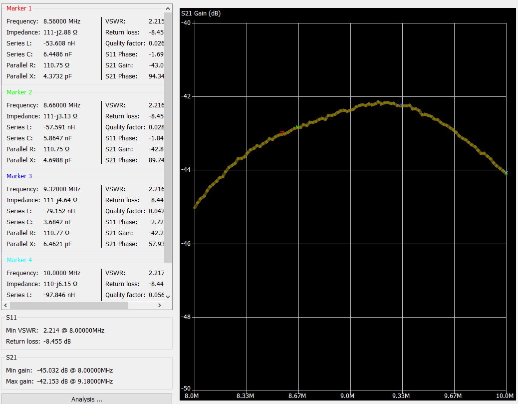 | 1,038 × 809 (57 KB) | Blwikiadmin (talk | contribs) |
You cannot overwrite this file.
File usage
The following page uses this file: