Difference between revisions of "Front Panel Assembly Sheet Rev 1"
Jump to navigation
Jump to search
Blwikiadmin (talk | contribs) |
Blwikiadmin (talk | contribs) |
||
| (22 intermediate revisions by the same user not shown) | |||
| Line 1: | Line 1: | ||
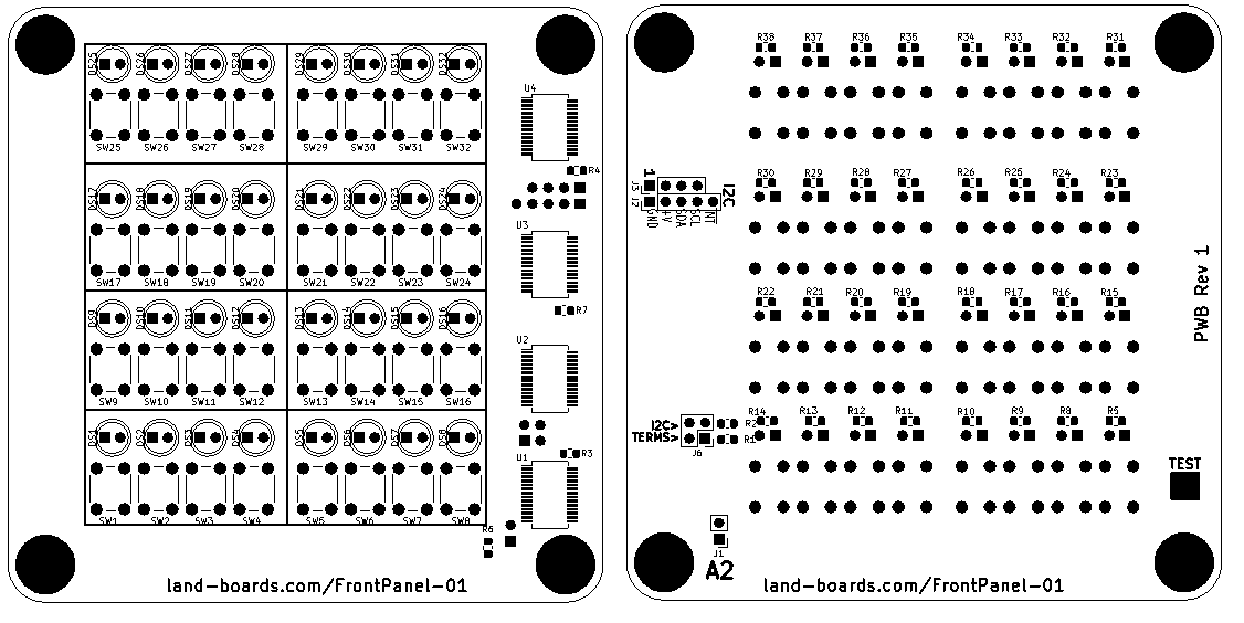
| − | == Parts List == | + | [[File:fp01_pwb_front_rear.png]] |
| + | |||
| + | == Parts List / Assembly Order == | ||
{| class="wikitable" | {| class="wikitable" | ||
| + | ! Qty | ||
| + | ! Value | ||
| + | ! RefDes | ||
| + | ! | ||
! Qty | ! Qty | ||
! Value | ! Value | ||
! RefDes | ! RefDes | ||
|- | |- | ||
| + | | 4 | ||
| + | | 10K, 0805 (Rear) | ||
| + | | R33, R36-R38 | ||
| + | | | ||
| 32 | | 32 | ||
| − | | LED | + | | LED, 5mm (NOTE 3) (Front) |
| − | | DS0 | + | | DS0-DS31 |
| − | |||
| − | |||
| − | |||
| − | |||
|- | |- | ||
| + | | 32 | ||
| + | | 1K, 0805 (NOTE 1) (Rear) | ||
| + | | R1-R32 | ||
| + | | | ||
| 1 | | 1 | ||
| − | | | + | | HEADER, RT ANG, 1x2 (Rear) |
| − | |||
| − | |||
| − | |||
| − | |||
| J1 | | J1 | ||
|- | |- | ||
| + | | 3 | ||
| + | | 2.2K, 0805 (NOTE 2) (Rear) | ||
| + | | R34-R36 | ||
| + | | | ||
| 1 | | 1 | ||
| − | | | + | | HEADER, RT ANG, 1x5 (Rear) |
| J2 | | J2 | ||
| − | |||
| − | |||
| − | |||
| − | |||
| − | |||
| − | |||
| − | |||
| − | |||
|- | |- | ||
| 32 | | 32 | ||
| − | | | + | | SW, Pushbutton, 6mm (Note 4) (Front) |
| − | + | | SW0-SW31 | |
| − | |- | + | | |
| − | |||
| − | |||
| − | |||
| − | | | ||
| 1 | | 1 | ||
| − | | | + | | HEADER, RT ANG, 1X4 (Rear) |
| − | | | + | | J3 |
|- | |- | ||
| 4 | | 4 | ||
| − | | MCP23017-E/SS | + | | [https://www.mouser.com/productdetail/microchip-technology/mcp23017-e-ss?qs=usxtMOJb1Ry4iqG%2FOK9gBg%3D%3D MCP23017-E/SS] (Front) |
| − | | U1, | + | | U1-U4 |
| + | | | ||
| + | | 1 | ||
| + | | HEADER, RT ANG, 2X2 (Rear) | ||
| + | | J4 | ||
|- | |- | ||
|} | |} | ||
| Line 54: | Line 56: | ||
== Notes == | == Notes == | ||
| − | Note 1 - | + | * Note 1 - 1K ballast LED resistors. Pick value for how bright you want LEDs at your operating voltage. |
| − | Note 2 - | + | * Note 2 - R34 and R35 are 2.2K I2C terminators. Needed for 3.3V operation and 400 KHz operation. R36 is INT* pullup. |
| − | Note 3 - | + | * Note 3 - LEDs - I like [https://www.ebay.com/itm/381087033256 diffused Orange LEDs]. I don't like clear LEDs. |
| + | * Note 4 - Pick the height you like. I like [https://www.ebay.com/itm/402850517873 6mm high]. You might like taller if you use keycaps. | ||
Latest revision as of 15:53, 20 June 2021
Parts List / Assembly Order
| Qty | Value | RefDes | Qty | Value | RefDes | |
|---|---|---|---|---|---|---|
| 4 | 10K, 0805 (Rear) | R33, R36-R38 | 32 | LED, 5mm (NOTE 3) (Front) | DS0-DS31 | |
| 32 | 1K, 0805 (NOTE 1) (Rear) | R1-R32 | 1 | HEADER, RT ANG, 1x2 (Rear) | J1 | |
| 3 | 2.2K, 0805 (NOTE 2) (Rear) | R34-R36 | 1 | HEADER, RT ANG, 1x5 (Rear) | J2 | |
| 32 | SW, Pushbutton, 6mm (Note 4) (Front) | SW0-SW31 | 1 | HEADER, RT ANG, 1X4 (Rear) | J3 | |
| 4 | MCP23017-E/SS (Front) | U1-U4 | 1 | HEADER, RT ANG, 2X2 (Rear) | J4 |
Notes
- Note 1 - 1K ballast LED resistors. Pick value for how bright you want LEDs at your operating voltage.
- Note 2 - R34 and R35 are 2.2K I2C terminators. Needed for 3.3V operation and 400 KHz operation. R36 is INT* pullup.
- Note 3 - LEDs - I like diffused Orange LEDs. I don't like clear LEDs.
- Note 4 - Pick the height you like. I like 6mm high. You might like taller if you use keycaps.
