Difference between revisions of "GPS Frequency Standard"
Jump to navigation
Jump to search
Blwikiadmin (talk | contribs) |
Blwikiadmin (talk | contribs) |
||
| Line 10: | Line 10: | ||
* [[PulseGen]] modified to receive input from GPS output and drive 50 Ohm output on BNC | * [[PulseGen]] modified to receive input from GPS output and drive 50 Ohm output on BNC | ||
* Fits into Aluminum Project Box Enclosure DIY 100*76*35mm - [https://www.ebay.com/sch/i.html?_from=R40&_trksid=p2334524.m570.l1313&_nkw=100*76*35mm+aluminum&_sacat=0&LH_TitleDesc=0&_odkw=100*76*35mm+Aluminum+PCB+Instrument+Box+Enclosure+Electronic+Project+Case+Set&_id=174408274566 ebay search] | * Fits into Aluminum Project Box Enclosure DIY 100*76*35mm - [https://www.ebay.com/sch/i.html?_from=R40&_trksid=p2334524.m570.l1313&_nkw=100*76*35mm+aluminum&_sacat=0&LH_TitleDesc=0&_odkw=100*76*35mm+Aluminum+PCB+Instrument+Box+Enclosure+Electronic+Project+Case+Set&_id=174408274566 ebay search] | ||
| + | |||
| + | === Wiring === | ||
| + | |||
| + | <pre> | ||
| + | # Wiring | ||
| + | # Signal Color From To | ||
| + | # GND Black QTPy49 J4-1 GPS pin 4 | ||
| + | # VCC Red QTPy49 J4-2 GPS pin 5 | ||
| + | # QTPy>GPS Blue QTPy49 J4-3 GPS pin 2 | ||
| + | # GPS>QTPy White QTPy49 J4-4 GPS pin 3 | ||
| + | # GND Black QTPy49 J5-1 PulseGen GND | ||
| + | # VCC Red QTPy49 J5-2 PulseGen VCC | ||
| + | # PPS Purple GPU pin 1 PulseGen In | ||
| + | # LED-VCC Red QTPy49 J9-3 D0 | ||
| + | # LED-GND Black QTPy49 J9-1 GND | ||
| + | <pre> | ||
| + | |||
| + | === Code === | ||
| + | |||
| + | * [https://github.com/land-boards/QT-Py/blob/main/CircuitPython/Seeed_XIAO_RP2040/GPS_004.py GPS_004.py] - Final working code | ||
| + | ** Saved as code.py to auto-run | ||
| + | * [https://github.com/land-boards/QT-Py/blob/main/CircuitPython/Seeed_XIAO_RP2040/GPS_003.py GPS_003.py] - Capture data from GPS module a line at a time - helpful for debugging | ||
| + | * [https://github.com/land-boards/QT-Py/blob/main/CircuitPython/Seeed_XIAO_RP2040/GPS_002.py GPS_002.py] - Read 32 bytes at a time | ||
| + | * [https://github.com/land-boards/QT-Py/blob/main/CircuitPython/Seeed_XIAO_RP2040/GPS_001.py GPS_001.py] - Formatted stings output | ||
== Build V1 == | == Build V1 == | ||
Revision as of 16:01, 26 June 2022
Contents
Build V2
Stand-alone design does not require PC
- NEO-7M GPS
- QTPy49 card
- QT Py (SAMD based)
- Running CircuitPython
- 3.3V, 40 MHz
- PulseGen modified to receive input from GPS output and drive 50 Ohm output on BNC
- Fits into Aluminum Project Box Enclosure DIY 100*76*35mm - ebay search
Wiring
# Wiring # Signal Color From To # GND Black QTPy49 J4-1 GPS pin 4 # VCC Red QTPy49 J4-2 GPS pin 5 # QTPy>GPS Blue QTPy49 J4-3 GPS pin 2 # GPS>QTPy White QTPy49 J4-4 GPS pin 3 # GND Black QTPy49 J5-1 PulseGen GND # VCC Red QTPy49 J5-2 PulseGen VCC # PPS Purple GPU pin 1 PulseGen In # LED-VCC Red QTPy49 J9-3 D0 # LED-GND Black QTPy49 J9-1 GNDCode
* GPS_004.py - Final working code ** Saved as code.py to auto-run * GPS_003.py - Capture data from GPS module a line at a time - helpful for debugging * GPS_002.py - Read 32 bytes at a time * GPS_001.py - Formatted stings outputBuild V1
* NEO-7M GPS * FTDI-49MM card set to 3.3V levels * Frequency set using ublox software on PC * PulseGen modified to receive output from GPS and drive 50 Ohm output out of the box * Fits into Aluminum Project Box Enclosure DIY 100*76*35mm - ebay searchGPS
* GPS Satellite Positioning Module NEO7M UBLOX * Specifications: * Working Voltage: 3.3v-5.0v * Color: As Picture Shown * Description: * With micro USB interface, you can debug GPS module with ordinary phone data cable, no longer need to use USB-TTL and other tools. * TTL interface is reserved to facilitate the use of USB-TTL or external microcontroller to control and receive GPS information. * Ceramic antenna on module board, no GPS external antenna can be used to search for stars. * Reserved SMA antenna interface, can use external antenna, star search ability is stronger.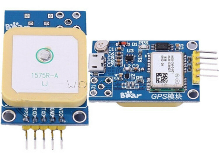
OLED Display
Description
* OLED display, no need backlight, self-illumination. * The display performance is better than the traditional LCD display, also lower consumption.Specifications
* Driver IC: SSD1306 * Size: 0.91 inch OLED * Resolution: 128 x 32 * Size: 38 * 12 mm * Number of pins: 4 Pin * Interface Type: IIC interface * Display Color: White * Operating temperature:-40 ~ 85 ℃I2C Pin Out
# GND: Power Ground # VCC: Power + (DC 3.3 ~5v) # SCL: Clock Line # SDA: Data Line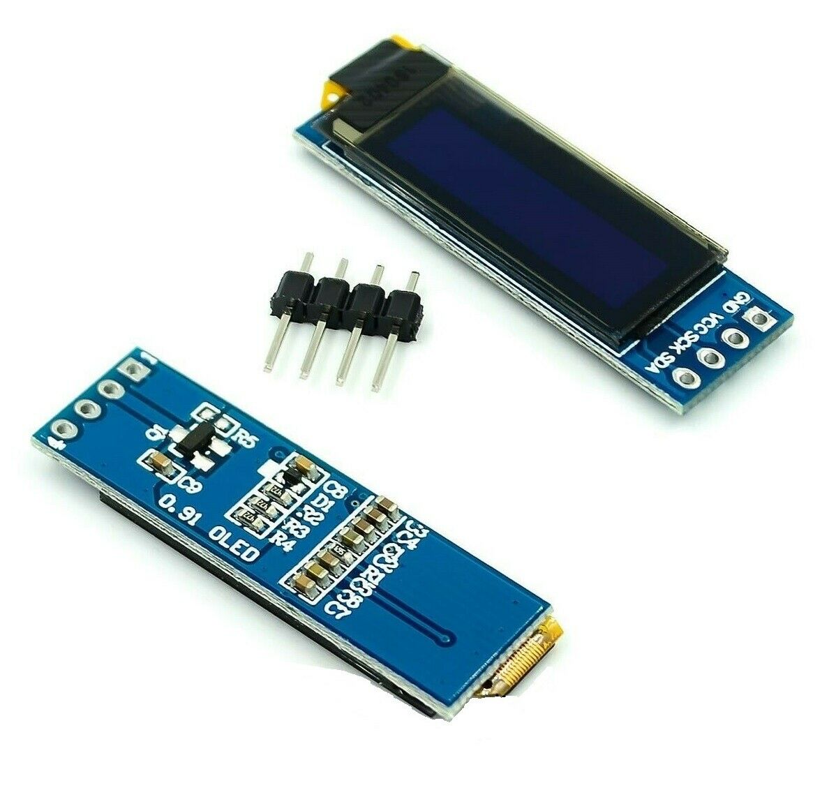
Reference Materials
* Design & Build a GPS locked Frequency Standard- Scullcom * SIMPLE 10 MHZ GPS FREQUENCY STANDARD AND RF GENERATOR ** uses Arduino Nano as FTDI replacement * An Arduino-based GPS Disciplined Oscillator * An Arduino Version of Brooks Shera's GPSDO * Simulating the Brooks Shera (W5OJM) GPSDO AlgorithmVideos

