Difference between revisions of "GPS Frequency Standard"
Jump to navigation
Jump to search
Blwikiadmin (talk | contribs) |
Blwikiadmin (talk | contribs) (→Wiring) |
||
| Line 24: | Line 24: | ||
=== Wiring === | === Wiring === | ||
| − | + | {| class="wikitable" | |
| − | + | ! Signal | |
| − | + | ! Color | |
| − | + | ! From | |
| − | + | ! To | |
| − | + | |- | |
| − | + | | GND | |
| − | + | | Black | |
| − | + | | QTPy49 J4-1 | |
| − | + | | GPS pin 4 | |
| − | + | |- | |
| − | + | | VCC | |
| − | + | | Red | |
| + | | QTPy49 J4-2 | ||
| + | | GPS pin 5 | ||
| + | |- | ||
| + | | QTPy>GPS | ||
| + | | Blue | ||
| + | | QTPy49 J4-3 | ||
| + | | GPS pin 2 | ||
| + | |- | ||
| + | | GPS>QTPy | ||
| + | | White | ||
| + | | QTPy49 J4-4 | ||
| + | | GPS pin 3 | ||
| + | |- | ||
| + | | GND | ||
| + | | Black | ||
| + | | QTPy49 J5-1 | ||
| + | | PulseGen GND | ||
| + | |- | ||
| + | | VCC | ||
| + | | Red | ||
| + | | QTPy49 J5-2 | ||
| + | | PulseGen VCC | ||
| + | |- | ||
| + | | PPS | ||
| + | | Purple | ||
| + | | GPU pin 1 | ||
| + | | PulseGen In | ||
| + | |- | ||
| + | | LED-VCC | ||
| + | | Red | ||
| + | | QTPy49 J9-3 | ||
| + | | D0 | ||
| + | |- | ||
| + | | LED-GND | ||
| + | | Black | ||
| + | | QTPy49 J9-1 | ||
| + | | GND | ||
| + | |- | ||
| + | |} | ||
=== Code === | === Code === | ||
Revision as of 12:45, 27 June 2022
Build V2
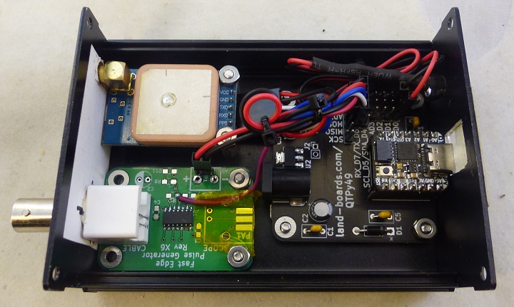
Stand-alone design does not require PC. Generates a 10 MHz output after satellite lock.
- NEO-7M GPS
- QTPy49 card
- CircuitPython code fits into QT Py (SAMD based) but a QT Py (RP2040 based) could be used
- 3.3V, 48 MHz
- Modified PulseGen card
- Oscillator circuit removed (not used as pulse generator)
- Receives input from GPS output and drives 50 Ohm output on BNC
- Status LED
- Blinks in for 1 second at power up
- Goes off until serial communications are working
- Blinks on-off as data is received from GPS while waiting for Satellite signal lock
- LED is on solid once output is enabled
- Fits into Aluminum Project Box Enclosure DIY 100*76*35mm - ebay search
- Inspired by Scullcom design
Wiring
| Signal | Color | From | To |
|---|---|---|---|
| GND | Black | QTPy49 J4-1 | GPS pin 4 |
| VCC | Red | QTPy49 J4-2 | GPS pin 5 |
| QTPy>GPS | Blue | QTPy49 J4-3 | GPS pin 2 |
| GPS>QTPy | White | QTPy49 J4-4 | GPS pin 3 |
| GND | Black | QTPy49 J5-1 | PulseGen GND |
| VCC | Red | QTPy49 J5-2 | PulseGen VCC |
| PPS | Purple | GPU pin 1 | PulseGen In |
| LED-VCC | Red | QTPy49 J9-3 | D0 |
| LED-GND | Black | QTPy49 J9-1 | GND |
Code
- FreqStdCap.ino - tool to generate bytestrings
- GPS_004.py - Final working code
- Saved as code.py to auto-run
- GPS_003.py - Capture data from GPS module a line at a time - helpful for debugging
- GPS_002.py - Read 32 bytes at a time
- GPS_001.py - Formatted stings output
Build V1
Requires PC running ublox software on PC to set output.
- NEO-7M GPS
- FTDI-49MM card set to 3.3V signal levels
- PulseGen modified to receive output from GPS and drive 50 Ohm output out of the box
- Fits into Aluminum Project Box Enclosure DIY 100*76*35mm - ebay search
GPS
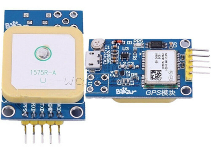
- GPS Satellite Positioning Module NEO7M UBLOX
- Specifications:
- Working Voltage: 3.3v-5.0v
- Color: As Picture Shown
- Description:
- With micro USB interface, you can debug GPS module with ordinary phone data cable, no longer need to use USB-TTL and other tools.
- TTL interface is reserved to facilitate the use of USB-TTL or external microcontroller to control and receive GPS information.
- Ceramic antenna on module board, no GPS external antenna can be used to search for stars.
- Reserved SMA antenna interface, can use external antenna, star search ability is stronger.
Reference Materials
- Design & Build a GPS locked Frequency Standard- Scullcom
- SIMPLE 10 MHZ GPS FREQUENCY STANDARD AND RF GENERATOR
- uses Arduino Nano as FTDI replacement
- An Arduino-based GPS Disciplined Oscillator
- An Arduino Version of Brooks Shera's GPSDO
- Simulating the Brooks Shera (W5OJM) GPSDO Algorithm
Videos

