Difference between pages "RF Attenuators" and "AudioAmp380"
(Difference between pages)
Jump to navigation
Jump to search
Blwikiadmin (talk | contribs) |
Blwikiadmin (talk | contribs) |
||
| Line 1: | Line 1: | ||
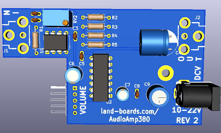
| − | + | [[FILE:AudioAmp380-3D.png]] | |
| − | == | + | == Design == |
| − | * [[ | + | * Pre-amp plus power amp |
| + | * 50 Ohm input impedance | ||
| + | * Gain trimmer potentiometer on preamp | ||
| + | * External mount gain potentiometer | ||
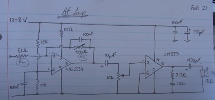
| + | * [https://www.ti.com/lit/ds/symlink/ne5534.pdf ] Pre-amplifier | ||
| + | * [https://www.ti.com/lit/ds/symlink/lm380.pdf LM380] 2.5W Audio Power Amplifier | ||
| + | * 12V nominal power | ||
| + | ** 10-22V | ||
| + | * Fits into 80x50x20mm extruded aluminum enclosure | ||
| + | ` | ||
| + | === Pre-Amplifier (NE5534) === | ||
| − | + | * Low-Noise Operational Amplifiers | |
| + | * Equivalent Input Noise Voltage 3.5 nV/√Hz Typ | ||
| + | * Unity-Gain Bandwidth 10 MHz Typ | ||
| + | * Common-Mode Rejection Ratio 100 dB Typ | ||
| + | * Wide Supply-Voltage Range ±3 V to ±20 V | ||
| + | * Used as single supply | ||
| − | === | + | === Audio Power Amplifier (LM380) === |
| − | * | + | * Wide Supply Voltage Range: 10V-22V |
| + | * Low Quiescent Power Drain: 0.13W (VS= 18V) | ||
| + | * Voltage Gain Fixed at 50 (34 dB) | ||
| + | * High Peak Current Capability: 1.3A | ||
| + | * Input Referenced to GND | ||
| + | * High Input Impedance: 150kΩ | ||
| + | * Low Distortion | ||
| + | * Quiescent Output Voltage is at One-Half of the Supply Voltage | ||
| − | + | == Controls == | |
| − | + | * RV1 - trade-off book gain/bandwidth - Tune for best sound | |
| + | * RV2 - volume control (after preamp and before LM380 Amp). 1x5 header wire to external pot | ||
| + | * J1 - Audio In, 50 Ohms input impedance | ||
| + | * J2 - Audio Out, 8 Ohm speakers | ||
| + | * J3 - Power, 10V-22VDC | ||
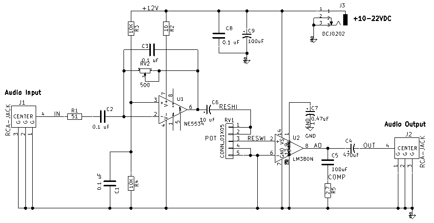
| − | + | == Rev 2 Schematic == | |
| − | == | ||
| − | + | [[file:AudioAmp380-Schematic.png]] | |
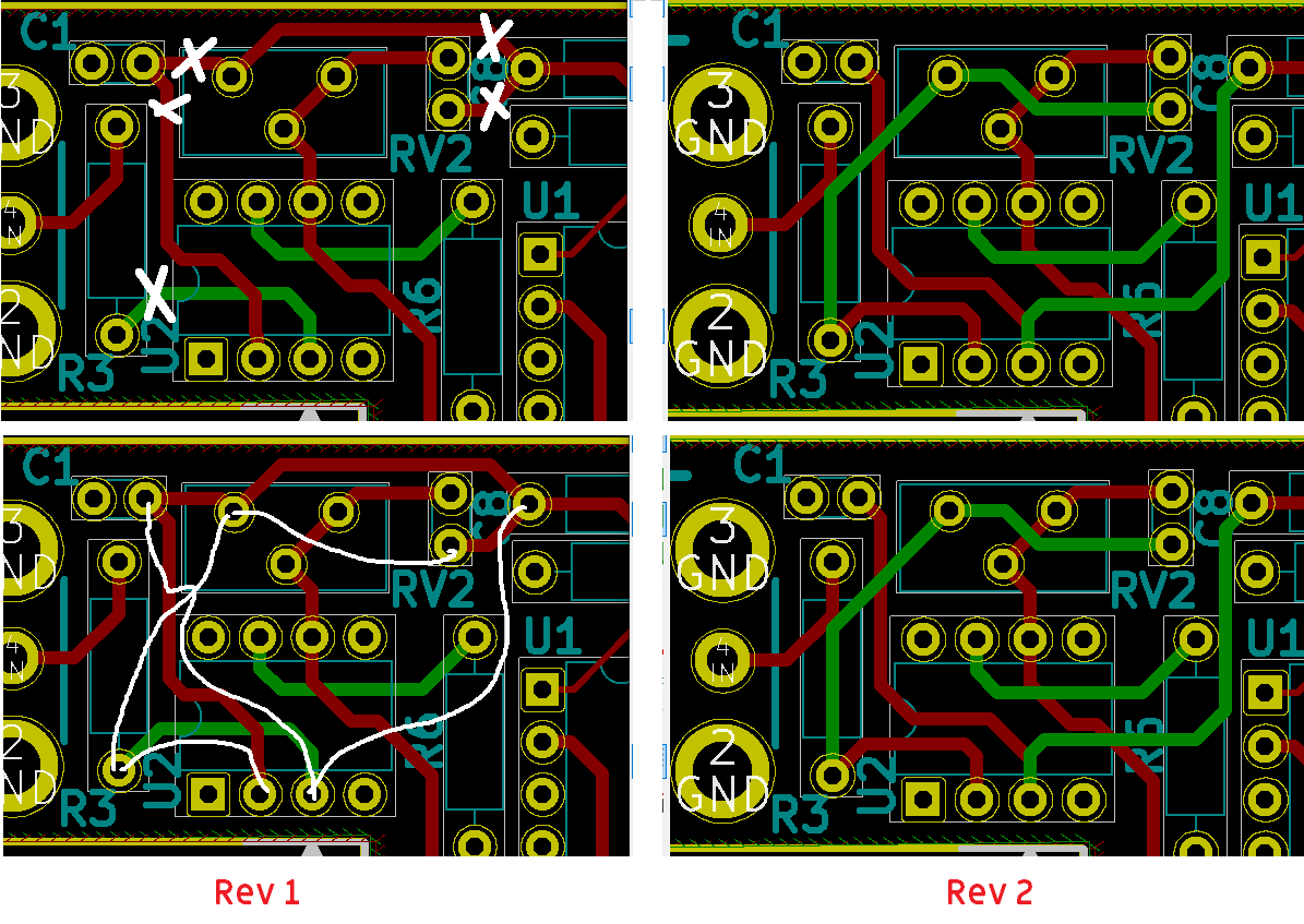
| − | + | == Rev 1 Rework == | |
| − | + | * Issues | |
| + | ** Front end opamp has + and - reversed | ||
| + | ** Also hooked up the feedback to the wrong input | ||
| + | * Replace R1 with jumper | ||
| + | * Replace C9 with jumper | ||
| + | * Remove C2 | ||
| + | * 5 Cuts | ||
| + | ** 4 on front | ||
| + | ** 1 on back | ||
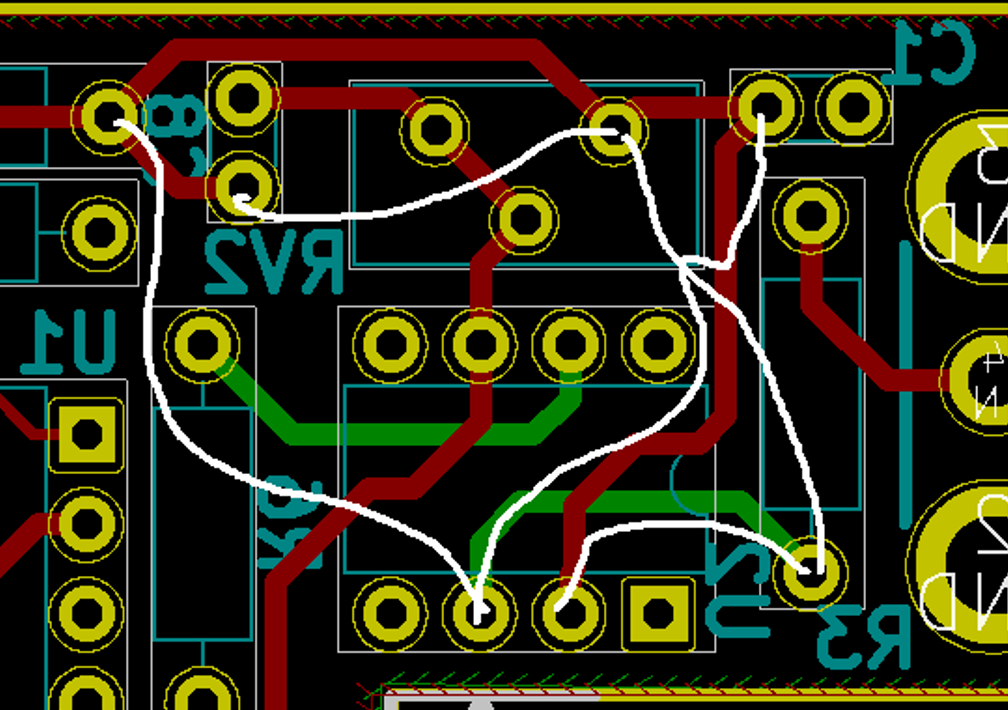
| + | * 5 jumper segments on back | ||
| + | ** 2 nodes | ||
| − | + | [[file:U2-2_3_Rev1_Rev2_Cuts_Jumpers.png]] | |
| − | |||
| − | |||
| − | |||
| − | |||
| − | |||
| − | |||
| − | |||
| − | |||
| − | |||
| − | |||
| − | * | + | * Jumpers on rear side |
| − | [[file: | + | [[file:AudioAmp380_Back_Jumpers.PNG]] |
| − | + | == Videos == | |
| − | + | [[file:ZL2CTM_Schematic.PNG]] | |
| − | + | <video type="youtube">GlT0HbvcmrM</video> | |
| − | == | + | == Assembly Sheet == |
| − | [[ | + | [[LM380 Rev 1 Assembly Sheet]] |
| − | |||
| − | |||
| − | |||
| − | |||
| − | |||
| − | |||
| − | |||
| − | |||
| − | |||
| − | |||
| − | |||
| − | |||
| − | |||
| − | |||
| − | |||
| − | |||
| − | |||
| − | |||
| − | |||
| − | |||
| − | |||
| − | |||
| − | |||
| − | |||
| − | |||
| − | |||
| − | |||
| − | |||
| − | |||
| − | |||
| − | |||
| − | |||
| − | |||
| − | |||
| − | |||
| − | |||
| − | |||
| − | |||
| − | |||
| − | |||
| − | |||
| − | |||
| − | |||
| − | |||
| − | |||
| − | |||
| − | |||
| − | |||
| − | |||
| − | |||
| − | |||
| − | |||
| − | |||
| − | |||
| − | |||
| − | |||
| − | |||
| − | |||
| − | |||
| − | |||
| − | |||
| − | |||
| − | |||
| − | |||
| − | |||
| − | |||
| − | |||
| − | |||
| − | |||
| − | |||
| − | |||
| − | |||
| − | |||
| − | |||
| − | |||
| − | |||
| − | |||
| − | |||
| − | |||
| − | |||
| − | |||
| − | |||
| − | |||
| − | |||
| − | |||
| − | |||
| − | |||
| − | |||
| − | |||
| − | |||
| − | |||
| − | |||
| − | |||
| − | |||
| − | |||
| − | |||
| − | |||
| − | |||
| − | |||
| − | |||
| − | |||
| − | |||
| − | |||
| − | |||
| − | |||
| − | |||
| − | |||
| − | |||
| − | |||
| − | |||
| − | |||
| − | |||
| − | |||
| − | |||
| − | |||
| − | |||
| − | |||
| − | |||
| − | |||
| − | |||
| − | |||
| − | |||
| − | |||
| − | |||
| − | |||
| − | |||
| − | |||
| − | |||
| − | |||
| − | |||
| − | |||
| − | |||
| − | |||
| − | |||
| − | |||
| − | |||
| − | |||
| − | |||
| − | |||
| − | |||
| − | |||
| − | |||
| − | |||
| − | |||
| − | |||
| − | |||
| − | |||
| − | |||
| − | |||
| − | |||
| − | |||
| − | |||
| − | |||
| − | |||
| − | |||
| − | |||
| − | |||
| − | |||
| − | |||
| − | |||
| − | |||
| − | |||
| − | |||
| − | |||
| − | |||
| − | |||
| − | |||
| − | |||
| − | |||
| − | |||
| − | |||
| − | |||
| − | |||
| − | |||
| − | |||
| − | |||
| − | |||
| − | |||
| − | |||
| − | |||
| − | |||
| − | |||
| − | |||
| − | |||
| − | |||
| − | |||
| − | |||
| − | |||
| − | |||
| − | |||
| − | |||
| − | |||
| − | |||
| − | |||
| − | |||
| − | |||
| − | |||
| − | |||
| − | |||
| − | |||
| − | |||
| − | |||
| − | |||
| − | |||
| − | |||
| − | |||
| − | |||
| − | |||
| − | |||
| − | |||
| − | |||
| − | |||
| − | |||
| − | |||
| − | |||
| − | |||
| − | |||
| − | |||
| − | |||
| − | |||
| − | |||
| − | |||
| − | |||
| − | |||
| − | |||
| − | |||
| − | |||
| − | |||
| − | |||
| − | |||
| − | |||
| − | |||
| − | |||
| − | |||
| − | |||
| − | |||
| − | |||
| − | |||
| − | |||
| − | |||
| − | |||
| − | |||
| − | |||
| − | |||
| − | |||
| − | |||
| − | |||
| − | |||
| − | |||
| − | |||
| − | |||
| − | |||
| − | |||
| − | |||
| − | |||
| − | |||
| − | |||
| − | |||
| − | |||
| − | |||
| − | |||
| − | |||
| − | |||
| − | |||
| − | |||
| − | |||
| − | |||
Revision as of 18:17, 24 October 2021
Contents
Design
- Pre-amp plus power amp
- 50 Ohm input impedance
- Gain trimmer potentiometer on preamp
- External mount gain potentiometer
- [1] Pre-amplifier
- LM380 2.5W Audio Power Amplifier
- 12V nominal power
- 10-22V
- Fits into 80x50x20mm extruded aluminum enclosure
`
Pre-Amplifier (NE5534)
- Low-Noise Operational Amplifiers
- Equivalent Input Noise Voltage 3.5 nV/√Hz Typ
- Unity-Gain Bandwidth 10 MHz Typ
- Common-Mode Rejection Ratio 100 dB Typ
- Wide Supply-Voltage Range ±3 V to ±20 V
- Used as single supply
Audio Power Amplifier (LM380)
- Wide Supply Voltage Range: 10V-22V
- Low Quiescent Power Drain: 0.13W (VS= 18V)
- Voltage Gain Fixed at 50 (34 dB)
- High Peak Current Capability: 1.3A
- Input Referenced to GND
- High Input Impedance: 150kΩ
- Low Distortion
- Quiescent Output Voltage is at One-Half of the Supply Voltage
Controls
- RV1 - trade-off book gain/bandwidth - Tune for best sound
- RV2 - volume control (after preamp and before LM380 Amp). 1x5 header wire to external pot
- J1 - Audio In, 50 Ohms input impedance
- J2 - Audio Out, 8 Ohm speakers
- J3 - Power, 10V-22VDC
Rev 2 Schematic
Rev 1 Rework
- Issues
- Front end opamp has + and - reversed
- Also hooked up the feedback to the wrong input
- Replace R1 with jumper
- Replace C9 with jumper
- Remove C2
- 5 Cuts
- 4 on front
- 1 on back
- 5 jumper segments on back
- 2 nodes
- Jumpers on rear side
Videos
