Difference between pages "File:PE4302 P1833-720px.jpg" and "VFO-003"
(Difference between pages)
Jump to navigation
Jump to search
Blwikiadmin (talk | contribs) |
Blwikiadmin (talk | contribs) |
||
| Line 1: | Line 1: | ||
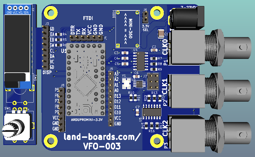
| + | [[fILE:VFO-003-B.png]] | ||
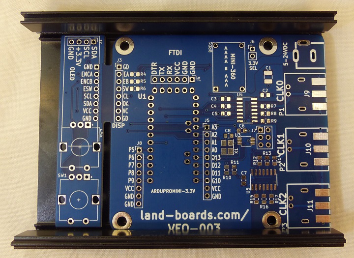
| + | [[fILE:P771-720px.jpg]] | ||
| + | |||
| + | == Features == | ||
| + | |||
| + | Software controlled VFO | ||
| + | |||
| + | * Arduino Pro Mini Microprocessor | ||
| + | ** 8-bit ATMEGA328 CPU | ||
| + | ** 8 MHz | ||
| + | ** 3.3V I/O | ||
| + | * Detachable Rotary Encoder/OLED card | ||
| + | ** SSD1306 OLED Display | ||
| + | *** I2C Interface | ||
| + | ** Controls frequencies with rotary encoder | ||
| + | ** 1Hz, 10 Hz, 100 Hz, 1 KHz, 10 KHz, 100 KHz, 1 MHz, 10 MHz steps (software controllable) | ||
| + | * Si5351A Oscillator | ||
| + | ** 3 Outputs | ||
| + | ** 27 MHz TCXO crystal | ||
| + | *** Adjustable to 0.01 Hz precision | ||
| + | ** I2C Interface | ||
| + | * 3.3V, 50 Ohm output | ||
| + | * Power | ||
| + | ** [[Mini360_Buck_Converter|MINI-360 DC/DC Buck regulator]] | ||
| + | ** 7-24 VDC | ||
| + | * Fits in standard extruded enclosures | ||
| + | |||
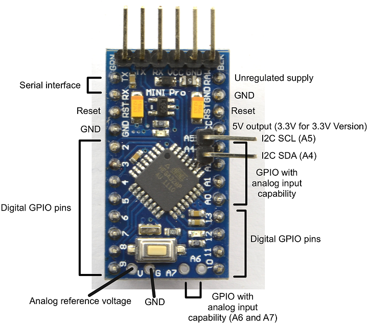
| + | === Arduino Pro Mini === | ||
| + | |||
| + | * [https://www.ebay.com/itm/5Pcs-Pro-Mini-3-3V-Arduino-Compatible-Board-8MHz/223719575050?ssPageName=STRK%3AMEBIDX%3AIT&_trksid=p2057872.m2749.l2649 ebay listing] | ||
| + | |||
| + | [[File:ArdruinoProMini-EBAY_PART-720px.png]] | ||
| + | |||
| + | == Connectors == | ||
| + | |||
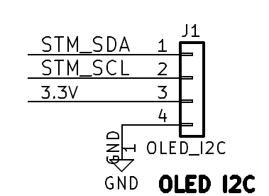
| + | === J1 - OLED === | ||
| + | |||
| + | # SDA | ||
| + | # SCL | ||
| + | # Vcc | ||
| + | # GND | ||
| + | |||
| + | [[file:VFO-003_J1.PNG]] | ||
| + | |||
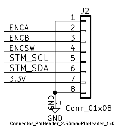
| + | === J2 - Display Encoder/OLED (Display card) === | ||
| + | |||
| + | # Encoder A | ||
| + | # Encoder B | ||
| + | # Encoder Switch | ||
| + | # SCL | ||
| + | # SDA | ||
| + | # Vcc | ||
| + | # GND | ||
| + | |||
| + | [[file:VFO-003_J2.PNG]] | ||
| + | |||
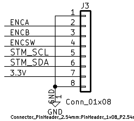
| + | === J3 - Display Encoder/OLED (Main card) === | ||
| + | |||
| + | # Encoder A | ||
| + | # Encoder B | ||
| + | # Encoder Switch | ||
| + | # SCL | ||
| + | # SDA | ||
| + | # Vcc | ||
| + | # GND | ||
| + | |||
| + | [[file:VFO-003_J3.PNG]] | ||
| + | |||
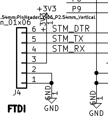
| + | === J4 - FTDI === | ||
| + | |||
| + | Can install 1x6 header on the Arduino Pro Mini and not install this | ||
| + | |||
| + | # GND | ||
| + | # GND | ||
| + | # Vcc | ||
| + | # RX | ||
| + | # Tx | ||
| + | # DTR | ||
| + | |||
| + | [[file:VFO-003_J4.PNG]] | ||
| + | |||
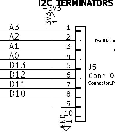
| + | === J5 - Arduino A0-A3/C10-D13 === | ||
| + | |||
| + | # A3 | ||
| + | # A2 | ||
| + | # A0 | ||
| + | # D13 | ||
| + | # D12 | ||
| + | # D11 | ||
| + | # D10 | ||
| + | # Vcc (not connected on Rev 1 PCB) | ||
| + | # GND (not connected on Rev 1 PCB) | ||
| + | |||
| + | [[file:VFO-003_J5.PNG]] | ||
| + | |||
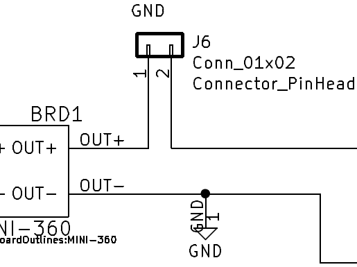
| + | === J6 - Disconnect for Mini-360 Power Supply === | ||
| + | |||
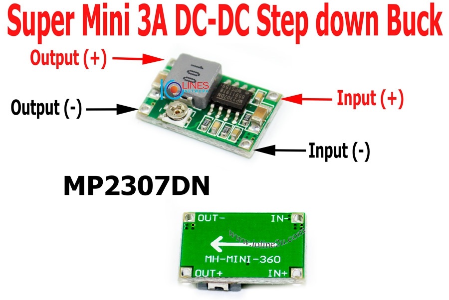
| + | * The [[Mini360 Buck Converter]] comes adjusted for a very high output voltage | ||
| + | * Remove jumper to adjust the output voltage to 3.3V without powering the rest of the card | ||
| + | * Install to power the card from the power supply | ||
| + | |||
| + | [[file:VFO-003_J6.PNG]] | ||
| + | |||
| + | [[file:Mini-360-004.jpg]] | ||
| + | |||
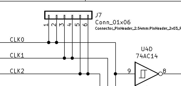
| + | === J7 - Output disconnects === | ||
| + | |||
| + | * Cut rear side trace to disconnect | ||
| + | * Can be used to install external LP filters | ||
| + | * Limited use due to 74AC14 drivers | ||
| + | |||
| + | [[file:VFO-003_J7.PNG]] | ||
| + | |||
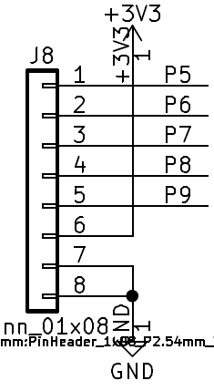
| + | === J7 - Arduino P5-P9 === | ||
| + | |||
| + | # P5 | ||
| + | # P6 | ||
| + | # P7 | ||
| + | # P8 | ||
| + | # P9 | ||
| + | # Vcc | ||
| + | # GND | ||
| + | |||
| + | [[file:VFO-003_J8.PNG]] | ||
| + | |||
| + | == Schematic == | ||
| + | |||
| + | * [https://github.com/land-boards/lb-boards/blob/master/HamRadio/VFO-003/Documents/Schematics/VFO-003_Rev3_Schematic.pdf Rev 3 schematic] | ||
| + | |||
| + | == Software == | ||
| + | |||
| + | * [https://github.com/land-boards/lb-Arduino-Code/tree/master/LBCards/VFO-003 GitHub Repository] | ||
| + | |||
| + | == Mechanicals == | ||
| + | |||
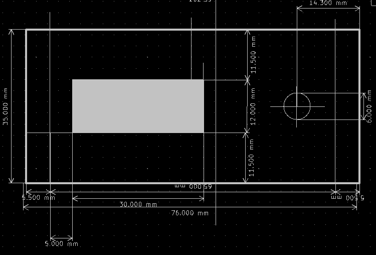
| + | [[file:VFO-003_FrontPanel_Holes.PNG]] | ||
| + | |||
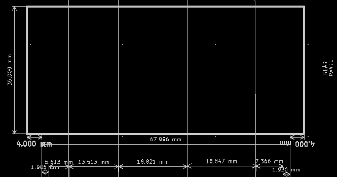
| + | [[file:VFO-003_RearPanel_Holes.PNG]] | ||
| + | |||
| + | == Assembly Sheet / Parts List == | ||
| + | |||
| + | [[VFO-003 Assembly Sheet - Rev 1]] | ||
Revision as of 14:28, 12 October 2021
Features
Software controlled VFO
- Arduino Pro Mini Microprocessor
- 8-bit ATMEGA328 CPU
- 8 MHz
- 3.3V I/O
- Detachable Rotary Encoder/OLED card
- SSD1306 OLED Display
- I2C Interface
- Controls frequencies with rotary encoder
- 1Hz, 10 Hz, 100 Hz, 1 KHz, 10 KHz, 100 KHz, 1 MHz, 10 MHz steps (software controllable)
- SSD1306 OLED Display
- Si5351A Oscillator
- 3 Outputs
- 27 MHz TCXO crystal
- Adjustable to 0.01 Hz precision
- I2C Interface
- 3.3V, 50 Ohm output
- Power
- MINI-360 DC/DC Buck regulator
- 7-24 VDC
- Fits in standard extruded enclosures
Arduino Pro Mini
Connectors
J1 - OLED
- SDA
- SCL
- Vcc
- GND
J2 - Display Encoder/OLED (Display card)
- Encoder A
- Encoder B
- Encoder Switch
- SCL
- SDA
- Vcc
- GND
J3 - Display Encoder/OLED (Main card)
- Encoder A
- Encoder B
- Encoder Switch
- SCL
- SDA
- Vcc
- GND
J4 - FTDI
Can install 1x6 header on the Arduino Pro Mini and not install this
- GND
- GND
- Vcc
- RX
- Tx
- DTR
J5 - Arduino A0-A3/C10-D13
- A3
- A2
- A0
- D13
- D12
- D11
- D10
- Vcc (not connected on Rev 1 PCB)
- GND (not connected on Rev 1 PCB)
J6 - Disconnect for Mini-360 Power Supply
- The Mini360 Buck Converter comes adjusted for a very high output voltage
- Remove jumper to adjust the output voltage to 3.3V without powering the rest of the card
- Install to power the card from the power supply
J7 - Output disconnects
- Cut rear side trace to disconnect
- Can be used to install external LP filters
- Limited use due to 74AC14 drivers
J7 - Arduino P5-P9
- P5
- P6
- P7
- P8
- P9
- Vcc
- GND
Schematic
Software
Mechanicals
Assembly Sheet / Parts List
File history
Click on a date/time to view the file as it appeared at that time.
| Date/Time | Thumbnail | Dimensions | User | Comment | |
|---|---|---|---|---|---|
| current | 22:21, 12 September 2021 |  | 720 × 359 (100 KB) | Blwikiadmin (talk | contribs) |
You cannot overwrite this file.
File usage
The following 2 pages use this file:
