Difference between revisions of "ODAS-RELAY-16"
Jump to navigation
Jump to search
Blwikiadmin (talk | contribs) (Created page with "link=https://www.tindie.com/stores/land_boards/ fILE:ODAS-RELAY-16-P356-720px.JPG == Features == * I2C bus ** Up to 400 KHz * MCP23017 I2C E...") |
Blwikiadmin (talk | contribs) |
||
| (4 intermediate revisions by the same user not shown) | |||
| Line 1: | Line 1: | ||
| − | [[File:tindie-mediums.png|link=https://www.tindie.com/ | + | [[File:tindie-mediums.png|link=https://www.tindie.com/products/13284/]] |
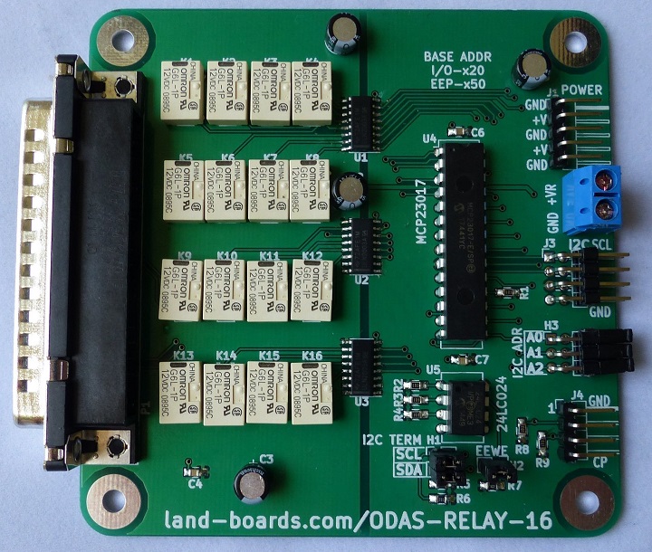
[[fILE:ODAS-RELAY-16-P356-720px.JPG]] | [[fILE:ODAS-RELAY-16-P356-720px.JPG]] | ||
| Line 5: | Line 5: | ||
== Features == | == Features == | ||
| + | * 16-channels of relays | ||
| + | ** SPST | ||
| + | ** Normally Open Relays | ||
| + | ** 1 FORM A | ||
| + | * Individual Relay Channel Drivers | ||
* I2C bus | * I2C bus | ||
** Up to 400 KHz | ** Up to 400 KHz | ||
| Line 10: | Line 15: | ||
** Extensive Library Support | ** Extensive Library Support | ||
* Three I2C address jumpers allow up to 8 cards | * Three I2C address jumpers allow up to 8 cards | ||
| − | + | * D-Sub DC-37 Male connector | |
| − | |||
| − | |||
| − | |||
| − | |||
| − | * D-Sub DC-37 connector | ||
** Two pins for contact pair | ** Two pins for contact pair | ||
* 3.3V or 5V I2C operation | * 3.3V or 5V I2C operation | ||
** Power via I2C connector or dedicated power connector | ** Power via I2C connector or dedicated power connector | ||
* Relay Power Connector | * Relay Power Connector | ||
| − | ** 12V | + | ** 12V - 5mm terminal block |
| − | + | * [https://www.mouser.com/ProductDetail/579-24LC024-P 24LC024] [[Open_Data_Acquisition_System#Personality_EEPROM|ODAS Personality EEPROM]] | |
| − | * | + | ** pid = 9 |
* ODAS Form Factor | * ODAS Form Factor | ||
** 95x95mm | ** 95x95mm | ||
| Line 109: | Line 109: | ||
Uses Adafruit Raspberry Pi driver Driver | Uses Adafruit Raspberry Pi driver Driver | ||
Alternate library Wiring Pi | Alternate library Wiring Pi | ||
| + | |||
| + | === Raspberry Pi Pico === | ||
| + | |||
| + | ==== MMBASIC ==== | ||
| + | |||
| + | * [https://github.com/land-boards/RasPiPico/blob/main/PicoMite_MMBASIC/PicoMite_VGA/Land%20Boards%20BASIC%20Programs/SWLEDX8-01.bas SWLEDX8-01.bas] - Read 8x switches, write 8x LEDs | ||
| + | * [https://github.com/land-boards/RasPiPico/blob/main/PicoMite_MMBASIC/PicoMite_VGA/Land%20Boards%20BASIC%20Programs/lbcards/GPIO16-02.bas MMBASIC Example Code] - Bounce a bit across the 16-bits (not for use with [[SWLEDX8]] card) | ||
== Layout == | == Layout == | ||
| Line 116: | Line 123: | ||
== Parts List / Assembly Sheet == | == Parts List / Assembly Sheet == | ||
| − | [[ODAS-RELAY-16 Assembly Sheet]] | + | * [[ODAS-RELAY-16 Assembly Sheet]] |
| − | [[ODAS-RELAY-16 Rev X1 Assembly Sheet]] | + | * [[ODAS-RELAY-16 Rev X1 Assembly Sheet]] |
== Changes in Rev X2 PWB == | == Changes in Rev X2 PWB == | ||
Latest revision as of 22:24, 31 May 2022
Contents
Features
- 16-channels of relays
- SPST
- Normally Open Relays
- 1 FORM A
- Individual Relay Channel Drivers
- I2C bus
- Up to 400 KHz
- MCP23017 I2C Expander
- Extensive Library Support
- Three I2C address jumpers allow up to 8 cards
- D-Sub DC-37 Male connector
- Two pins for contact pair
- 3.3V or 5V I2C operation
- Power via I2C connector or dedicated power connector
- Relay Power Connector
- 12V - 5mm terminal block
- 24LC024 ODAS Personality EEPROM
- pid = 9
- ODAS Form Factor
- 95x95mm
Headers
H1 - I2C Termination
Install to terminate I2C on this card Open to terminate I2C elsewhere in the I2C chain
H2 - EEWE - EEPROM Write Enable
Install to allow writes to EEPROM Remove to prevent writes to EEPROM
H3 - I2C Base Address Select Jumpers
Three jumper positions Address A0-A2
Connectors
J1 - Logic Power
3.3V or 5V logic power
- GND
- VCC (Logic)
- GND
- VCC (Logic)
- GND
J2 - Relay Power
- +V(Relay) - 12V
- GND
- J3 - I2C Daisy-Chain Connector
- SCL
- SDA
- VCC
- GND
J4 - Card Detect/Interrupt
- GND
- INTA
- INTB
- CARD PRESENT - active low
P1 - DC-37 Relay Contact Pairs
Pin	Conn	Pin	Conn
19	R1-C	37	R1-NO
18	R2-C	36	R2-NO
17	R3-C	35	R3-NO
16	R4-C	34	R4-NO
15	R5-C	33	R5-NO
14	R6-C	32	R6-NO
13	R7-C	31	R7-NO
12	R8-C	30	R8-NO
11	R9-C	29	R9-NO
10	R10-C	28	R10-NO
9	R11-C	27	R11-NO
8	R12-C	26	R12-NO
7	R13-C	25	R13-NO
6	R14-C	24	R14-NO
5	R15-C	23	R15-NO
4	R16-C	22	R15-NO
3	N/C	21	N/C
2	N/C	20	GND
1	GND
C = Relay common connection
NO = Normally Open relay contact
N/C = No Connection
Drivers
Driver is any MCP23017 driver.
Arduino Driver
Uses Adafruit driver Adafruit_MCP23017 Example code at ODAS-RELAY-16 Example Code. Raspberry Pi Driver Uses Adafruit Raspberry Pi driver Driver Alternate library Wiring Pi
Raspberry Pi Pico
MMBASIC
- SWLEDX8-01.bas - Read 8x switches, write 8x LEDs
- MMBASIC Example Code - Bounce a bit across the 16-bits (not for use with SWLEDX8 card)
Layout
ODAS-RELAY-16-X2-Dimensioned.PNG
Parts List / Assembly Sheet
Changes in Rev X2 PWB
Narrower footprint for K1-K16 relay parts Changed relays to to 4x4 array Issues with Rev X1 PWB Pad spacing on relays is too wide Part is narrower than a normal 8 pin DIP
Rev X1 Layout
ODAS-RELAY-16-X1-Dimensioned.PNG

