Difference between revisions of "PIATX"
Jump to navigation
Jump to search
Blwikiadmin (talk | contribs) (Created page with "== Raspberry Pi to ATX Computer Case Cable Connections Card == File:PIATX-P1010203-640px.jpg * Connect up to the cables inside an ATX case * Cables documented in Intel F...") |
Blwikiadmin (talk | contribs) |
||
| Line 105: | Line 105: | ||
[[File:MicroUSB.jpg]] | [[File:MicroUSB.jpg]] | ||
| − | Rev X1 rework | + | == Rev X1 rework == |
| − | Cut etch J2-3 to J2-4 | + | |
| − | Add wire J2-3 to J1-13 (HDACT) | + | * Cut etch J2-3 to J2-4 |
| − | Remove R6 | + | * Add wire J2-3 to J1-13 (HDACT) |
| − | Install R3 only in pad next to R3 silkscreen. | + | * Remove R6 |
| − | Attach wire from other side of R3 to adjacent via | + | * Install R3 only in pad next to R3 silkscreen. |
| − | Rev X2 PL | + | * Attach wire from other side of R3 to adjacent via |
| + | |||
| + | == Rev X2 PL == | ||
| + | |||
| + | <pre> | ||
Qty Value RefDes | Qty Value RefDes | ||
3 120 R1,R5,R6 | 3 120 R1,R5,R6 | ||
| Line 122: | Line 126: | ||
1 RASPIO J1 | 1 RASPIO J1 | ||
1 USB-MICRO-B J3 | 1 USB-MICRO-B J3 | ||
| + | </pre> | ||
| − | Rev X1 PL/Assembly | + | == Rev X1 PL/Assembly == |
| − | |||
| − | + | [[PIATX Assembly Sheet Rev X1]] | |
| − | |||
| − | |||
| − | |||
| − | |||
| − | |||
| − | |||
| − | |||
| − | |||
| − | |||
| − | |||
| − | |||
| − | |||
| − | |||
| − | |||
| − | |||
| − | |||
| − | |||
| − | |||
| − | |||
| − | |||
| − | |||
| − | |||
| − | |||
| − | |||
| − | |||
| − | |||
| − | |||
| − | |||
Latest revision as of 11:52, 10 January 2020
Contents
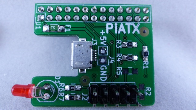
Raspberry Pi to ATX Computer Case Cable Connections Card
- Connect up to the cables inside an ATX case
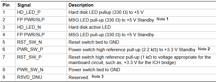
- Cables documented in Intel Front Panel I/O Connectivity Design Guide
- On Board LED
- 26 pin connector to Raspberry Pi
- Works with all versions of the P1
- Power the Pi from the USB connector
- The ATX case power button can be used with a script to initiate shutdown when the case power button is pressed
- The ATX case reset button can be used with a script to initiate reboot when the button is pressed
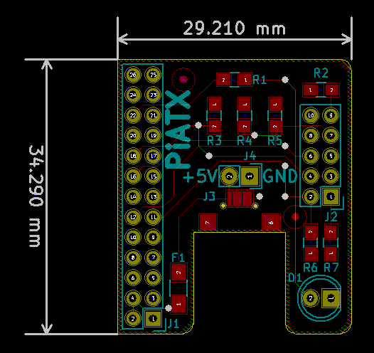
Layout
Connectors
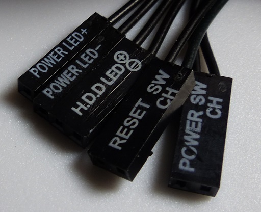
LED Switches Cable
Chassis cables
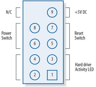
Motherboard Header Pinout
Chassis Schematic
Connector Top View
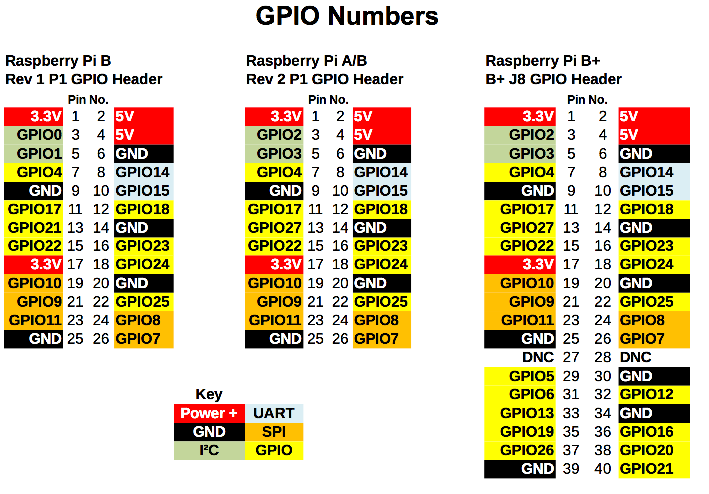
Pi Connector
Desc	Pin	Pin	Desc
+3.3V (N/A)	1	2	+5V
NA	3	4	+5V
NA	5	6	GND
NA	7	8	NA
GND	9	10	NA
PWR_LED+
GPIO_17

11	12	RESET_N
GPIO_18

HARD DRIVE
GPIO_21

13	14	GND
15	16	POWER SWITCH
GPIO_23

NA	17	18	PWR_LED-
GPIO_24

NA	19	20	GND
NA	21	22	ON-BOARD LED
GPIO_25

NA	23	24	NA
GND	25	26	NA
J2 Connector
Desc	Pin		Pin	Desc
HDD LED Pos
120 Ohm Pullup to +3.3V

1		2	PWR LED 1
GPIO_17

HDD Active LED Neg
GPIO_27

3		4	PWR LED 2
GPIO_24

Reset Switch Return
GND

5		6	Power Switch
Pulled up to +3.3V GPIO_23

Reset Switch
Pulled up to +3.3V GPIO_18

7		8	Power Switch return
GND

Key	9		10	Key
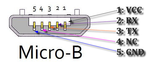
J3 USB Micro Connector
Rev X1 rework
- Cut etch J2-3 to J2-4
- Add wire J2-3 to J1-13 (HDACT)
- Remove R6
- Install R3 only in pad next to R3 silkscreen.
- Attach wire from other side of R3 to adjacent via
Rev X2 PL
Qty	Value	RefDes
3	120	R1,R5,R6
2	2.2K	R2,R3
1	DNP	R4
1	LED	D1
1	FUSE	F1
1	CONN_01X02	J4
1	CONN_02X05	J2
1	RASPIO	J1
1	USB-MICRO-B	J3
