Difference between revisions of "QTPy49-01 Rev 1 Assembly Sheet"
Jump to navigation
Jump to search
Blwikiadmin (talk | contribs) (→Notes) |
Blwikiadmin (talk | contribs) |
||
| Line 37: | Line 37: | ||
| 1 | | 1 | ||
| U2 | | U2 | ||
| − | | [https://www.mouser.com/ProductDetail/ | + | | [https://www.mouser.com/ProductDetail/Diodes-Incorporated/AZ1117H-5.0TRG1?qs=5V6w%252Be2aIqZ8sF7chzoKCQ%3D%3D AZ1117H-5.0] |
| | | | ||
| 7 | | 7 | ||
Latest revision as of 15:47, 19 August 2022
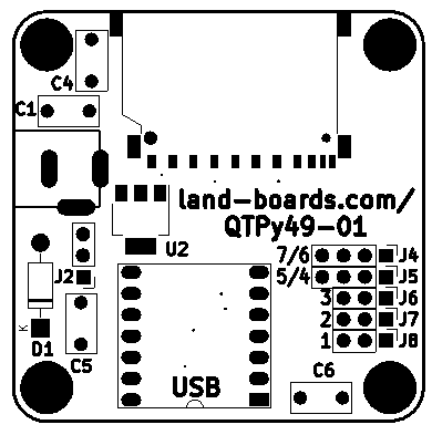
Parts List
| Find | Qty | Ref Des | Part Number | Find | Qty | Ref Des | Part Number | |
|---|---|---|---|---|---|---|---|---|
| 1 | 3 | C1, C5, C6 | 0.1uF (0.2" pitch) | 5 | 2 | J4, J5 | Header, Strt, 1x4 | |
| 2 | 1 | D1 | 1N5819 (DO-14) | 6 | 3 | J6, J7, J8 | Header, Strt, 1x3 | |
| 3 | 1 | U2 | AZ1117H-5.0 | 7 | 1 | J2 | Header, Strt, 1x3 (opt) | |
| 4 | 1 | BRD1 | Note 1 | 8 | 1 | J3 | SD_Card | |
| 9 | 1 | C4 | 47uF | 10 | 1 | J1 | Conn, DC |
Notes
1 - BRD1 can be
- Adafruit QT Py SAMD21 Product Page
- Seeeduino XIAO SAMD21 Product Page
- Adafruit QT Py RP2040 Product page
- Seeed XIAO RP2040 Product page
2 - Minimum value of C4 needs to match Voltage Regulator output capacitance requirements
- Typically 10 uF
- 47uF is a safe value
- Negative lead of capacitor goes up towards board edge
