QT Py
Contents
- 1 Two Versions of the QT Py
- 2 RP2040 vs SAM version
- 3 Pins (SAMD version)
- 3.1 3V
- 3.2 5V
- 3.3 A0 / D0 - Digital/analog GPIO pin 0
- 3.4 A1 / D1 - Digital/analog GPIO pin 1
- 3.5 A2 / D2 - Digital/analog GPIO pin 2
- 3.6 A3 / D3 - Digital/analog GPIO pin 3
- 3.7 SDA / D4
- 3.8 SCL / D5
- 3.9 TX / A6 / D6
- 3.10 RX / A7 / D7
- 3.11 SCK / A8 / D8
- 3.12 MISO / A9 / D9
- 3.13 MOSI / A10 / D10
- 3.14 NeoPixel
- 4 Programming
- 5 Flash EEPROM 2 MB
- 6 QT Py Breakout Board
- 7 QTPy49 Board
- 8 Videos
Two Versions of the QT Py
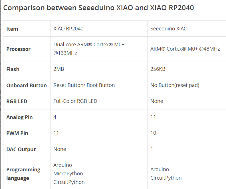
- AdaFruit and Seeed Studio have SAMD21 and RP2040 versions of the QT Py (XIAO on Seeed Studio)
- Same form factors
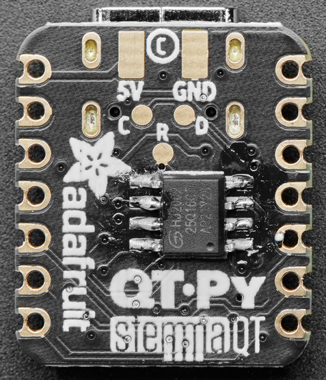
- QT Py (SAMD based)
- QT Py (RP2040 based)
RP2040 vs SAM version
- RP2040 is faster (125 MHz vs 48 MHz)
- RP2040 has 2 cores vs 1
- RP2040 has more Flash
- RP2040 has more SRAM
- The RP2040 version is more expensive, but about the same cost if the SAM version is used with an external Flash
- SAMD21/RP2040 Arduino Boards – Which 32-bit Microcontrollers should you use?
Pins (SAMD version)
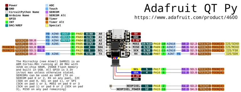 (Click on image for larger file)
3V
- Regulated output from the onboard regulator. You can draw 500mA
5V
- 5v out from the USB port.
- Voltage input
- Requires external diode
- Schottky, signal, power
- Between external power source and this pin
- Cannot power the USB port by supplying 5V to this pin
- There is a protection diode that prevents the 5V from reaching the USB connector.
- This is to protect host computer USB ports, etc.
- Requires external diode
A0 / D0 - Digital/analog GPIO pin 0
- Digital I/O 0
- Analog In 0
- True analog output with 10 bit precision
- Does not have PWM
- Capacitive touch input.
A1 / D1 - Digital/analog GPIO pin 1
- Digital I/O 1
- Analog In 1
- Capacitive touch input
- AREF pin.
A2 / D2 - Digital/analog GPIO pin 2
- Digital I/O 2
- Analog In 2
- PWM
- Capacitive touch input.
A3 / D3 - Digital/analog GPIO pin 3
- Digital I/O 3
- Analog In 3
- PWM output
- Capacitive touch input.
SDA / D4
- Digital I/O 4
- I2C SDA pin
- PWM output
- No analog on this pin
- No pull up on this pin
- When using with I2C requires an external 2.2K-10K pullup to 3.3V.
SCL / D5
- Digital I/O 5
- I2C SCL
- No analog on this pin
- No pull up on this pin
- When using with I2C requires an external 2.2K-10K pullup to 3.3V.
TX / A6 / D6
- Digital I/O 6
- Transmit (output) for Serial1
- Analog 6
- PWM output
- Capacitive touch input
RX / A7 / D7
- Digital I/O 7
- Receive (input) for Serial1
- Analog 7
- PWM output
- Capacitive touch input
SCK / A8 / D8
- Digital I/O 8
- SPI SCK pin
- Analog 8
- PWM output
MISO / A9 / D9
- Digital I/O 8
- SPI MISO pin
- Analog 8
- PWM output
MOSI / A10 / D10
- Digital I/O 10
- SPI MOSI pin
- Analog 10
- PWM output
NeoPixel
- Connected to digital pin 11 for signal
- Set pin 12 low for low power usage
- By default pin 12 is set high by Arduino/CircuitPython
- Code example
import board
import neopixel

pixels = neopixel.NeoPixel(board.NEOPIXEL, 1)
# fill((rVal, gVal, bVal))
# rVal, gVal, bVal = red/green/blue values (0-255)
pixels.fill((255, 0, 0))  # Note double parens
Programming
- C/C++ or CircuitPython
C/C++
- Arduino IDE Setup for SAMD version
- Requires Arduino IDE version 1.8 or higher
- Add https://adafruit.github.io/arduino-board-index/package_adafruit_index.json to Preferences Additional Boards Manager URLs
- Add Adafruit SAMD Boards in Boards Manager
- RP2040 C/C++ SDK
CircuitPython/MicroPython
Install CircuitPython on QT Py RP2040
- Hold down the BOOT (right) button while plugging it into USB
- Download [ UF2 from Adafruit QT Py CircuitPython RP2040
- Drive will open
- Drop UF2 onto drive
>>> import gc
>>> gc.mem_free()
208128
>>> import time
>>> gc.mem_free()
207952
CircuitPython
CircuitPython for SAMD
- Adafruit CircuitPython 7.3.0 on 2021-01-21
- CircuitPython is a derivative of MicroPython
- CircuitPython looks for a code file on the board to run
- There are four options: code.txt, code.py, main.txt and main.py
- CircuitPython looks for those files, in that order, and then runs the first one it finds
- QT_Py_blink.py
- QT Py Haxpress used with 2MB Flash EEPROM
- Mu code editor
- Free memory
- Reports 17,776 bytes of free space
import gc
gc.mem_free()
Updating CircuitPython
- Save the contents of CIRCUITPY, just in case
- Double-click the reset button to show the BOOT drive
- Drag the update-bootloader .uf2 file to the BOOT drive
- Wait a few tens of seconds for the bootloader to update; the BOOT drive will reappear
- Check INFO_UF2.TXT to verify that the bootloader version has been updated. Then you will need to reload CircuitPython.
- Update mpy files
Land Boards CircuitPython Code
I2CIO-8 (MCP23008) Drivers
- GitHub Repo
- I2CIO8.py Demo code - Bounce an LED across MCP23008 card output pins
- I2CIO8_RW.py - Read jumpers, write back LEDs
SWLEDX8-I2C (MCP23017) Drivers
- SWLEDX8.py = Control the SWLEDX8-I2C card
PROTO16-I2C (MCP23017) Drivers
- PROTO16_Blink.py - Control the PROTO16-I2C card
Digital I/O Example
import board
import digitalio
import time

led = digitalio.DigitalInOut(board.D13)
led.direction = digitalio.Direction.OUTPUT

while True:
    led.value = True
    time.sleep(0.1)
    led.value = False
    time.sleep(0.5)
Flash EEPROM 2 MB
QT Py Breakout Board
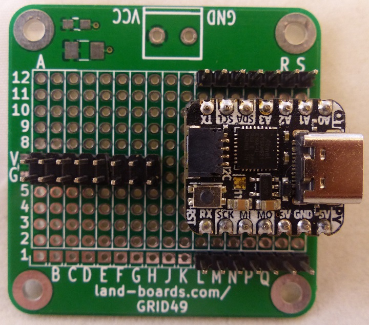
- Built onto GRID49 card
- Socket for QT Py
- QT Py pins brought to header strips
- 3.3V power distribution on 2x8 header
Pins (CCW direction)
- S12 = A0
- R12 = A1
- Q12 = A2
- P12 = A3
- N12 = SDA
- M12 = SCL
- L12 = TX
- L1 = RX
- M1 = SCK
- N1 = MI
- P1 = MO
- Q1 = 3.3V
- R1 = GND
- S1 = 5V
- A6=B6=C6=D6=E6=F6=G6=H6 = GND
- A7=B7=C7=D7=E7=F7=G7=H7 = 3.3V
QTPy49 Board
Videos
