Difference between revisions of "QT Py (RP2040 based)"
Jump to navigation
Jump to search
Blwikiadmin (talk | contribs) |
Blwikiadmin (talk | contribs) |
||
| (165 intermediate revisions by the same user not shown) | |||
| Line 1: | Line 1: | ||
| + | [[File:tindie-mediums.png|link=https://www.tindie.com/products/27066/]] | ||
| + | |||
| + | [[FILE:QTPy49_P18254-720px.jpg]] | ||
| + | |||
| + | <video type="youtube">iI9lUsVSuF8</video> | ||
| + | |||
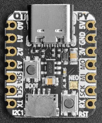
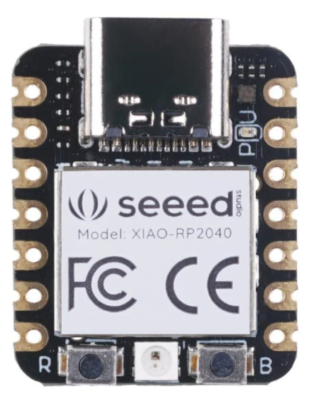
[[file:QT Py RP2040.PNG]] [[file:XIAO-RP2040.PNG]] | [[file:QT Py RP2040.PNG]] [[file:XIAO-RP2040.PNG]] | ||
== RP2040 QT Py == | == RP2040 QT Py == | ||
| − | + | * Two manufacturers | |
| + | ** [https://www.adafruit.com/product/4900 Adafruit QT Py RP2040 Product page] | ||
| + | ** [https://www.seeedstudio.com/XIAO-RP2040-v1-0-p-5026.html Seeed XIAO RP2040 Product page] | ||
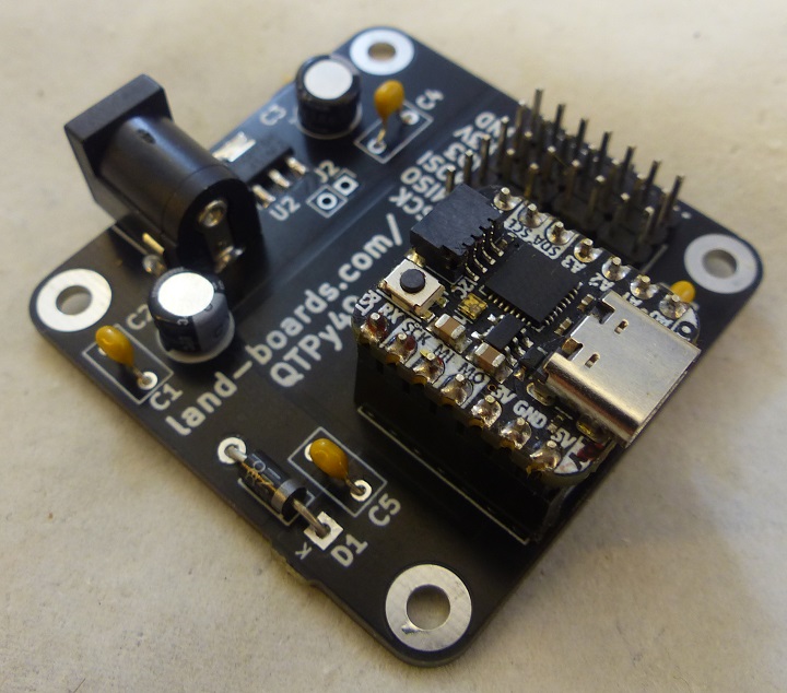
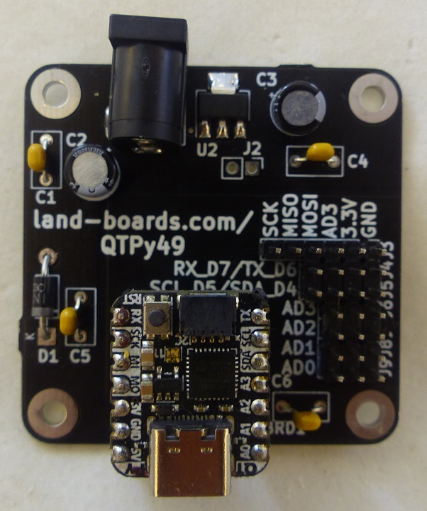
| + | * [[QTPy49|QTPy49 Breakout card]] | ||
| + | |||
| + | == Features == | ||
| − | |||
| − | |||
* RP2040 32-bit Cortex M0+ dual-core | * RP2040 32-bit Cortex M0+ dual-core | ||
* Runs at ~125 MHz | * Runs at ~125 MHz | ||
* 264 KB RAM | * 264 KB RAM | ||
| − | * | + | * SPI FLASH chip for storing files and CircuitPython/MicroPython code storage |
| − | + | ** 8 MB - Adafruit | |
| − | * Can be used with MicroPython or CircuitPython | + | ** 2 MB - Seeedstudio |
| + | * No EEPROM | ||
| + | * Can be used with C/C++ (Arduino), MicroPython, or CircuitPython | ||
* Built-in RGB NeoPixel LED | * Built-in RGB NeoPixel LED | ||
* 13 GPIO pins (11 breakout pads and two QT pads): | * 13 GPIO pins (11 breakout pads and two QT pads): | ||
** Four 12 bit ADCs (one more than Pico) | ** Four 12 bit ADCs (one more than Pico) | ||
| − | ** | + | ** I2C port |
| + | *** 2 I2C: 1 on QT pins, one on the (Adafruit) breakout pads - Adafruit | ||
| + | *** 1 I2C on XAIO | ||
** SPI and UART peripherals, in standard QT Py locations, | ** SPI and UART peripherals, in standard QT Py locations, | ||
** PWM outputs on every IO pin - for servos, LEDs, etc | ** PWM outputs on every IO pin - for servos, LEDs, etc | ||
| Line 22: | Line 35: | ||
* 3.3V logic and power 600 mA | * 3.3V logic and power 600 mA | ||
* Both Reset button and Bootloader select buttons for quick restarts (no unplugging-replugging to relaunch code) | * Both Reset button and Bootloader select buttons for quick restarts (no unplugging-replugging to relaunch code) | ||
| + | * USB Type C connector | ||
| − | == Pins (RP2040 | + | == Pins (RP2040) == |
| − | * Pins are | + | * Pins are mapped differently in MicroPython between Seeeduino XIA and Adafruit QT Py |
| + | * The Python board module virtualizes the difference | ||
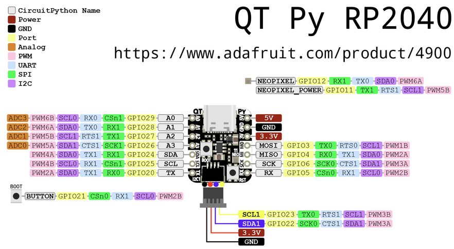
=== Adafruit RP2040 === | === Adafruit RP2040 === | ||
| + | |||
| + | [https://www.adafruit.com/product/4900 Adafruit QT Py RP2040 Product page] | ||
[[file:adafruit_products_qtpy-rp2040-pins.png]] | [[file:adafruit_products_qtpy-rp2040-pins.png]] | ||
| Line 151: | Line 168: | ||
* Power = Pin 12 - set low for low power usage | * Power = Pin 12 - set low for low power usage | ||
* By default pin 12 is set high by Arduino/CircuitPython | * By default pin 12 is set high by Arduino/CircuitPython | ||
| − | * Code example | + | * [https://learn.adafruit.com/adafruit-qt-py-2040/built-in-neopixel-led NeoPixel Code example] |
<pre> | <pre> | ||
| Line 163: | Line 180: | ||
</pre> | </pre> | ||
| − | === Seeeduino RP2040 === | + | === Seeeduino XIAO RP2040 === |
| + | |||
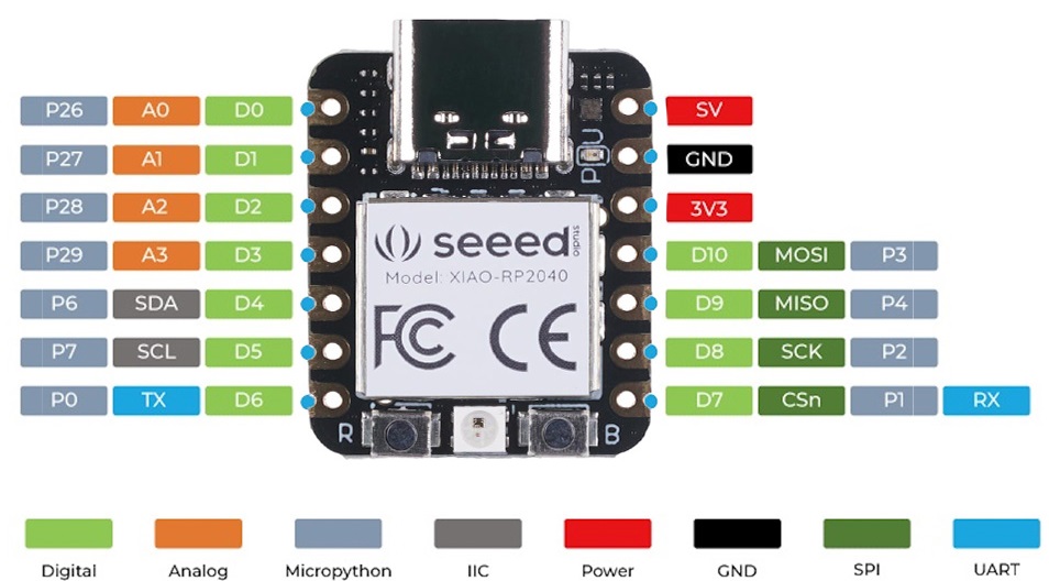
| + | There are 14 GPIO PINs on XIAO RP2040, on which there are 11 digital pins, 4 analog pins, 11 PWM Pins,1 I2C interface, 1 UART interface, 1 SPI interface, 1 SWD Bonding pad interface. | ||
| + | |||
| + | * [https://www.seeedstudio.com/XIAO-RP2040-v1-0-p-5026.html Seeed XIAO RP2040 product page] | ||
| + | * [https://wiki.seeedstudio.com/XIAO-RP2040/ Seeed XIAO RP2040 wiki page] | ||
[[file:seeed-xinpin-rp2040.jpg]] | [[file:seeed-xinpin-rp2040.jpg]] | ||
| Line 184: | Line 206: | ||
==== A0 / D0 / P26 - Digital/analog GPIO pin 0 ==== | ==== A0 / D0 / P26 - Digital/analog GPIO pin 0 ==== | ||
| − | * | + | * board.D0 |
| − | * | + | * board.A0 |
* P26 in Arduino/MicroPython | * P26 in Arduino/MicroPython | ||
* True analog output with 10 bit precision | * True analog output with 10 bit precision | ||
| − | * | + | * PWM output |
| − | |||
| − | ==== A1 / D1 - Digital/analog GPIO pin 1 ==== | + | ==== A1 / D1 / P27 - Digital/analog GPIO pin 1 ==== |
| − | * | + | * board.D1 |
| + | * board.A1 | ||
* P27 in Arduino/MicroPython | * P27 in Arduino/MicroPython | ||
| − | * | + | * PWM output |
| − | |||
| − | |||
| − | ==== A2 / D2 - Digital/analog GPIO pin 2 ==== | + | ==== A2 / D2 / P28 - Digital/analog GPIO pin 2 ==== |
| − | * | + | * board.D2 |
| − | * P28 in MicroPython | + | * board.A2 |
| − | + | * P28 in Arduino/MicroPython | |
| − | * PWM | + | * PWM output |
| − | |||
| − | ==== A3 / D3 - Digital/analog GPIO pin 3 ==== | + | ==== A3 / D3 / P29 - Digital/analog GPIO pin 3 ==== |
| − | * | + | * board.D3 |
| + | * board.A3 | ||
* P29 in Arduino/MicroPython | * P29 in Arduino/MicroPython | ||
| − | |||
* PWM output | * PWM output | ||
| − | |||
| − | ==== SDA / D4 ==== | + | ==== SDA / D4 / P6 ==== |
| − | * | + | * board.D4 |
| − | * | + | * board.SDA |
| + | * P6 in Arduino/MicroPython | ||
* I2C SDA pin | * I2C SDA pin | ||
* PWM output | * PWM output | ||
| − | |||
* No pull up on this pin | * No pull up on this pin | ||
| − | * When using with I2C requires an external 2.2K-10K pullup to 3.3V. | + | * When using with I2C requires an external 2.2K-10K pullup to 3.3V. |
| − | ==== SCL / D5 ==== | + | ==== SCL / D5 / P7 ==== |
| − | * | + | * board.D5 |
| + | * board.SCL | ||
* P7 in Arduino/MicroPython | * P7 in Arduino/MicroPython | ||
* I2C SCL | * I2C SCL | ||
| − | |||
* No pull up on this pin | * No pull up on this pin | ||
| − | * When using with I2C requires an external 2.2K-10K pullup to 3.3V | + | * When using with I2C requires an external 2.2K-10K pullup to 3.3V |
| + | * PWM output | ||
| − | ==== TX / | + | ==== TX / D6 / P0 ==== |
| − | * | + | * board.D6 |
| + | * board.TX | ||
* Transmit (output) for Serial1 | * Transmit (output) for Serial1 | ||
* P0 in Arduino/MicroPython | * P0 in Arduino/MicroPython | ||
| − | |||
* PWM output | * PWM output | ||
| − | |||
| − | ==== RX / | + | ==== RX / D7 / P1 ==== |
| − | * | + | * board.D7 |
| + | * board.RX | ||
* Receive (input) for Serial1 | * Receive (input) for Serial1 | ||
* P1 in Arduino/MicroPython | * P1 in Arduino/MicroPython | ||
| − | |||
* PWM output | * PWM output | ||
| − | |||
| − | ==== SCK / | + | ==== SCK / D8 / P2 ==== |
| − | * | + | * board.D8 |
| + | * board.SCK | ||
* SPI SCK pin | * SPI SCK pin | ||
* P2 in Arduino/MicroPython | * P2 in Arduino/MicroPython | ||
| − | |||
* PWM output | * PWM output | ||
| − | ==== MISO / | + | ==== MISO / D9 / P4 ==== |
| − | * | + | * board.D8 |
| + | * board.MISO | ||
* SPI MISO pin | * SPI MISO pin | ||
* P4 in Arduino/MicroPython | * P4 in Arduino/MicroPython | ||
| − | |||
* PWM output | * PWM output | ||
| − | ==== MOSI / | + | ==== MOSI / D10 / P3 ==== |
| − | * | + | * board.D10 |
| + | * board.MOSI | ||
* SPI MOSI pin | * SPI MOSI pin | ||
* P3 in Arduino/MicroPython | * P3 in Arduino/MicroPython | ||
| − | |||
* PWM output | * PWM output | ||
| Line 282: | Line 299: | ||
* Red Power LED | * Red Power LED | ||
* USER LED (RGB) | * USER LED (RGB) | ||
| − | ** RED - | + | ** RED - P17 |
| − | ** GRN - | + | *** board.LED_RED |
| + | ** GRN - P16 | ||
| + | *** board.LED_GREEN | ||
*** LED_BUILTIN in Arduino | *** LED_BUILTIN in Arduino | ||
| − | ** BLU - | + | ** BLU - P25 |
| + | *** board.LED_BLUE | ||
** [https://github.com/land-boards/lb-Arduino-Code/tree/master/LBCards/QTPyRP2040/Blink3 Code to Blink 3 LEDs] | ** [https://github.com/land-boards/lb-Arduino-Code/tree/master/LBCards/QTPyRP2040/Blink3 Code to Blink 3 LEDs] | ||
* NEOPIXEL LED Features | * NEOPIXEL LED Features | ||
| Line 293: | Line 313: | ||
** Communication: PWM through data pin | ** Communication: PWM through data pin | ||
** Driver IC: WS2812 | ** Driver IC: WS2812 | ||
| − | ** NEOPIXEL Power - | + | ** NEOPIXEL Power - P11 - set low for low power usage |
| − | ** NEOPIXEL Data - | + | *** board.NEOPIXEL_POWER |
| + | ** NEOPIXEL Data - P12 | ||
| + | *** board.NEOPIXEL | ||
** [https://github.com/land-boards/lb-Arduino-Code/tree/master/LBCards/QTPyRP2040/NEOPIXEL_Demo NEOPIXEL Demo] | ** [https://github.com/land-boards/lb-Arduino-Code/tree/master/LBCards/QTPyRP2040/NEOPIXEL_Demo NEOPIXEL Demo] | ||
== Programming == | == Programming == | ||
| − | * C/C++ | + | * The RP2040 can be programmed in several languages/environments |
| − | * CircuitPython | + | ** C/C++ |
| − | * MicroPython | + | ** CircuitPython - best choice in most cases |
| + | ** MicroPython | ||
=== C/C++ === | === C/C++ === | ||
| − | + | * Can program in C/C++ using | |
| − | + | ** Arduino IDE | |
| − | + | ** Pico C++ SDK | |
| − | ** | ||
| − | ** | ||
| − | |||
| − | ==== C/C++ Adafruit RP2040 ==== | + | ==== C/C++ Adafruit RP2040 - Arduino ==== |
* [https://learn.adafruit.com/adafruit-qt-py-2040/arduino-ide-setup Arduino IDE Setup] | * [https://learn.adafruit.com/adafruit-qt-py-2040/arduino-ide-setup Arduino IDE Setup] | ||
* Add the URL to the the Additional Boards Manager URLs | * Add the URL to the the Additional Boards Manager URLs | ||
| − | + | <pre> | |
| + | https://github.com/earlephilhower/arduino-pico/releases/download/global/package_rp2040_index.json | ||
| + | </pre> | ||
* Tools > Board > Boards Manager | * Tools > Board > Boards Manager | ||
* Search for RP2040 | * Search for RP2040 | ||
| Line 324: | Line 346: | ||
* Navigate to the Raspberry Pi RP2040 Boards menu and choose Adafruit QT Py RP2040 | * Navigate to the Raspberry Pi RP2040 Boards menu and choose Adafruit QT Py RP2040 | ||
| − | === CircuitPython/MicroPython === | + | ==== C/C++ Seeeduino RP2040 - Arduino ==== |
| + | |||
| + | * [https://wiki.seeedstudio.com/XIAO-RP2040-with-Arduino/ Arduino IDE Setup for Seeeduino RP2040 version] | ||
| + | ** Requires Arduino IDE version 1.8 or higher | ||
| + | ** Add the URL to the the Additional Boards Manager URLs | ||
| + | <pre> | ||
| + | https://files.seeedstudio.com/arduino/package_seeeduino_boards_index.json | ||
| + | </pre> | ||
| + | * [https://github.com/land-boards/lb-Arduino-Code/tree/master/LBCards/QTPyRP2040 Arduino Repository] | ||
| + | |||
| + | ==== C/C++ RP2040 ==== | ||
| + | |||
| + | * [https://github.com/raspberrypi/pico-sdk Raspberry Pi Pico C/C++ SDK] | ||
| + | |||
| + | === CircuitPython === | ||
| + | |||
| + | * [https://circuitpython.readthedocs.io/en/latest/README.html CircuitPython] is a derivative of [https://github.com/micropython/micropython/tree/master/ports/rp2 MicroPython] | ||
| + | * CircuitPython is the best choice in most use-cases | ||
| + | ** Board specific support for both Seeed XAIO and Adafruit QT Py cards | ||
| + | * [https://learn.adafruit.com/welcome-to-circuitpython Welcome To CircuitPython] - Adafruit tutorial | ||
| + | * Autorun code - CircuitPython looks for a code file on the board to run | ||
| + | ** There are four options: code.txt, code.py, main.txt and main.py | ||
| + | ** CircuitPython looks for those files, in that order, and then runs the first one it finds | ||
| + | * [https://codewith.mu/ Mu code editor] | ||
| + | ** [https://codewith.mu/en/download Mu editor download] | ||
| + | |||
| + | ==== CircuitPython for Adafruit QT Py RP2040 ==== | ||
| − | |||
| − | |||
* [https://learn.adafruit.com/adafruit-qt-py-2040 Adafruit QT Py RP2040 Overview] | * [https://learn.adafruit.com/adafruit-qt-py-2040 Adafruit QT Py RP2040 Overview] | ||
| + | * [https://learn.adafruit.com/adafruit-qt-py-2040/circuitpython-essentials CircuitPython Essentials] | ||
| + | * [https://learn.adafruit.com/adafruit-qt-py-2040/circuitpython CircuitPython for Adafruit QT Py RP2040] | ||
| − | ==== Install CircuitPython on QT Py RP2040 ==== | + | ===== Install CircuitPython on Adafruit QT Py RP2040 ===== |
| + | * [https://circuitpython.org/board/adafruit_qtpy_rp2040/ Adafruit CircuitPython Download page] | ||
| + | ** Running v7.3.0 | ||
* Hold down the BOOT (right) button while plugging it into USB | * Hold down the BOOT (right) button while plugging it into USB | ||
| − | * Download | + | * Download [https://circuitpython.org/board/adafruit_qtpy_rp2040/ UF2 from Adafruit QT Py CircuitPython RP2040] |
* Drive will open | * Drive will open | ||
* Drop UF2 onto drive | * Drop UF2 onto drive | ||
| + | * Blink program | ||
| + | ** [https://github.com/adafruit/Adafruit_Learning_System_Guides/blob/master/Welcome_to_CircuitPython/QT_Py_blink.py QT_Py_blink.py] | ||
| + | |||
| + | ===== Updating CircuitPython on Adafruit QT Py RP2040 ===== | ||
| + | |||
| + | * Save the contents of CIRCUITPY, just in case | ||
| + | * '''Double-click the reset button''' to show the BOOT drive | ||
| + | * Drag the update-bootloader .uf2 file to the BOOT drive | ||
| + | * Wait a few tens of seconds for the bootloader to update; the BOOT drive will reappear | ||
| + | * Check INFO_UF2.TXT to verify that the bootloader version has been updated. Then you will need to reload CircuitPython. | ||
| + | * [http://adafru.it/mpy-update Update mpy files] | ||
| + | |||
| + | ==== CircuitPython for Seeed XIAO RP2040 ==== | ||
| + | |||
| + | * [https://wiki.seeedstudio.com/XIAO-RP2040-with-CircuitPython/ XIAO RP2040 with CircuitPython] | ||
| + | * [https://github.com/land-boards/QT-Py/tree/main/CircuitPython/Seeed_XIAO_RP2040 Our GitHub repo] | ||
| + | * Use [https://thonny.org/ Thonny IDE] | ||
| + | ** Left click bottom right corner | ||
| + | ** Select CircuitPython (generic) | ||
| + | ** Left click bottom right corner | ||
| + | ** Select Configure Interpreter | ||
| + | ** Select USB Serial Device (COM<x) | ||
| + | * Pins list | ||
| + | |||
| + | <pre> | ||
| + | import board | ||
| + | dir(board) | ||
| + | ['__class__', '__name__', 'A0', 'A1', 'A2', 'A3', 'D0', 'D1', 'D10', 'D2', 'D3', 'D4', 'D5', 'D6', 'D7', 'D8', 'D9', 'I2C', 'LED', 'LED_BLUE', 'LED_GREEN', 'LED_RED', 'MISO', 'MOSI', 'NEOPIXEL', 'NEOPIXEL_POWER', 'RX', 'SCK', 'SCL', 'SDA', 'SPI', 'TX', 'UART', 'board_id'] | ||
| + | |||
| + | >>> print(board.board_id) | ||
| + | seeeduino_xiao_rp2040 | ||
| + | </pre> | ||
| + | |||
| + | ===== Install CircuitPython on Seeed XIAO RP2040 ===== | ||
| + | |||
| + | * Hold down the "BOOT" button. (The "B" is written on the board shown to the right) | ||
| + | * Connect the XIAO RP2040 to your computer while you still pressing the button. | ||
| + | * The computer then will appear a disk driver(RP1-RP2) | ||
| + | * Download the [https://files.seeedstudio.com/wiki/XIAO-RP2040/res/XIAO-RP2040-CircuitPython.uf2 XIAO-RP2040-CircuitPython.uf2 file] for XIAO RP2040 | ||
| + | * Drag the .uf2 file to the disk driver("RP1-RP2") | ||
| + | * Check the disk drive if the name has changed to "CIRCUITPY" (takes a few seconds) | ||
| + | * Free memory | ||
<pre> | <pre> | ||
| Line 346: | Line 438: | ||
</pre> | </pre> | ||
| − | === CircuitPython === | + | ==== CircuitPython Example Code ==== |
| − | + | * [https://github.com/land-boards/QT-Py/blob/main/CircuitPython/Seeed_XIAO_RP2040/i2cscan.py i2cscan.py] - Print list of I2C devices found | |
| − | |||
| − | |||
| − | * [https://github.com/ | ||
| − | |||
| − | |||
| − | ==== | + | ===== SSD1306 Display Examples ===== |
| − | * [https:// | + | * [https://github.com/land-boards/QT-Py/blob/main/CircuitPython/Seeed_XIAO_RP2040/ssd1306_TextFB.py ssd1306_TextFB.py] - Displays 21 columns and 8 rows of text |
| − | * [https:// | + | * [https://github.com/land-boards/QT-Py/blob/main/CircuitPython/Seeed_XIAO_RP2040/ssd1306_bouncing_ball.py ssd1306_bouncing_ball.py] - Bounce a ball |
| − | * | + | * [https://github.com/land-boards/QT-Py/blob/main/CircuitPython/Seeed_XIAO_RP2040/ssd1306_framebuftest.py ssd1306_framebuftest.py] - Frame buffer demo |
| − | * | + | * [https://github.com/land-boards/QT-Py/blob/main/CircuitPython/Seeed_XIAO_RP2040/ssd1306_simpletest_FB.py ssd1306_simpletest_FB.py] - Draws 3 pixels |
| − | |||
| − | |||
| − | |||
| − | |||
| − | ===== | + | ===== Digital I/O Examples ===== |
| − | * | + | * [https://learn.adafruit.com/adafruit-qt-py-2040/blink Blink on Adafruit QT Py RP2040] |
| − | + | * [https://github.com/land-boards/QT-Py/blob/main/CircuitPython/Seeed_XIAO_RP2040/Blink.py Blink.py] | |
| − | |||
| − | |||
| − | |||
| − | * [ | ||
| − | ==== Land Boards | + | ===== Land Boards I2CIO-8 (MCP23008) Examples ===== |
| − | |||
| − | |||
| − | |||
| − | |||
* [https://github.com/land-boards/lb-boards/tree/master/Projects/QTPy/Land%20Boards/Land%20Boards%20QT%20Py%20Code GitHub Repo] | * [https://github.com/land-boards/lb-boards/tree/master/Projects/QTPy/Land%20Boards/Land%20Boards%20QT%20Py%20Code GitHub Repo] | ||
** [https://github.com/land-boards/lb-boards/blob/master/Projects/QTPy/Land%20Boards/Land%20Boards%20QT%20Py%20Code/I2CIO8.py I2CIO8.py Demo code] - Bounce an LED across MCP23008 card output pins | ** [https://github.com/land-boards/lb-boards/blob/master/Projects/QTPy/Land%20Boards/Land%20Boards%20QT%20Py%20Code/I2CIO8.py I2CIO8.py Demo code] - Bounce an LED across MCP23008 card output pins | ||
** [https://github.com/land-boards/lb-boards/blob/master/Projects/QTPy/Land%20Boards/Land%20Boards%20QT%20Py%20Code/I2CIO8_RW.py I2CIO8_RW.py] - Read jumpers, write back LEDs | ** [https://github.com/land-boards/lb-boards/blob/master/Projects/QTPy/Land%20Boards/Land%20Boards%20QT%20Py%20Code/I2CIO8_RW.py I2CIO8_RW.py] - Read jumpers, write back LEDs | ||
| + | <pre> | ||
| + | >>> dir(i2c) | ||
| + | ['__class__', '__enter__', '__exit__', 'deinit', 'readfrom_into', 'scan', 'try_lock', 'unlock', 'writeto', 'writeto_then_readfrom'] | ||
| + | </pre> | ||
| − | ===== SWLEDX8-I2C (MCP23017) | + | ===== Land Boards SWLEDX8-I2C (MCP23017) Examples ===== |
* [https://github.com/land-boards/lb-boards/blob/master/Projects/QTPy/Land%20Boards/Land%20Boards%20QT%20Py%20Code/SWLEDX8.py SWLEDX8.py] = Control the [[SWLEDX8-I2C]] card | * [https://github.com/land-boards/lb-boards/blob/master/Projects/QTPy/Land%20Boards/Land%20Boards%20QT%20Py%20Code/SWLEDX8.py SWLEDX8.py] = Control the [[SWLEDX8-I2C]] card | ||
| − | ===== PROTO16-I2C (MCP23017) | + | ===== Land Boards PROTO16-I2C (MCP23017) Examples ===== |
* [https://github.com/land-boards/lb-boards/blob/master/Projects/QTPy/Land%20Boards/Land%20Boards%20QT%20Py%20Code/PROTO16_Blink.py PROTO16_Blink.py] - Control the [[PROTO16-I2C]] card | * [https://github.com/land-boards/lb-boards/blob/master/Projects/QTPy/Land%20Boards/Land%20Boards%20QT%20Py%20Code/PROTO16_Blink.py PROTO16_Blink.py] - Control the [[PROTO16-I2C]] card | ||
| − | === | + | === MicroPython === |
| − | + | * [https://github.com/micropython/micropython/tree/master/ports/rp2 RP2040 MicroPython Repo] | |
| − | + | * [https://thonny.org/ Thonny Editor] | |
| − | |||
| − | |||
| − | + | ==== MicroPython on XIAO RP2040 ==== | |
| − | |||
| − | + | * [https://wiki.seeedstudio.com/XIAO-RP2040-with-MicroPython/ XIAO RP2040 with MicroPython] | |
| − | + | * Software Setup | |
| − | + | # Download and Install the latest version of Thonny editor according to your operating system | |
| − | + | # Launch the Thonny IDE | |
| − | + | # Click "Tools→Options" to open the settings. | |
| − | + | # Step 4. Chose the "Interpreter" interface and select the device as "MicroPython(Raspberry Pi Pico)" and the port as "Try to detect prot automatically" | |
| + | # Press and hold the "BOOT" button and then connect the XIAO RP2040 to the PC through the Type-C cable. If it works well, there is an "RPI-RP2" desk shown on the PC. | ||
| + | # Press the "Stop/Restart Backend" button and there will be a pop-up window that helps you install the MicroPython firmware on the board. The XIAO RP2040 uses the same chip as the Raspberry Pi Pico, thereby the XIAO RP2040 is compatible with Pico's MicroPython files. | ||
| + | # Write code ([https://files.seeedstudio.com/wiki/XIAO-RP2040/img/micropython/ws2812.py Neopixel example]) | ||
| + | # Upload the codes by clicking the "Run current script" button. For the first time, Thonny will ask where you want to save your codes file. Both This Computer and Raspberry Pi Pico are fine. | ||
| − | == | + | === MMBASIC on XIAO RP2040 === |
| − | + | [[MMBASIC on XIAO RP2040]] | |
| − | |||
| − | [[ | ||
== QT Py Breakout Board == | == QT Py Breakout Board == | ||
| Line 448: | Line 526: | ||
* [[QTPy49]] | * [[QTPy49]] | ||
| − | [[ | + | [[file:QTPy49-P18253-720pxV.jpg]] |
== Videos == | == Videos == | ||
| + | |||
| + | <video type="youtube">u61mOIfGdR8</video> | ||
<video type="youtube">qfbPyu_1L18</video> | <video type="youtube">qfbPyu_1L18</video> | ||
Latest revision as of 09:56, 12 October 2022
Contents
- 1 RP2040 QT Py
- 2 Features
- 3 Pins (RP2040)
- 3.1 Adafruit RP2040
- 3.1.1 3V
- 3.1.2 5V
- 3.1.3 A0 / D0 - Digital/analog GPIO pin 0
- 3.1.4 A1 / D1 - Digital/analog GPIO pin 1
- 3.1.5 A2 / D2 - Digital/analog GPIO pin 2
- 3.1.6 A3 / D3 - Digital/analog GPIO pin 3
- 3.1.7 SDA / D4
- 3.1.8 SCL / D5
- 3.1.9 TX / A6 / D6
- 3.1.10 RX / A7 / D7
- 3.1.11 SCK / A8 / D8
- 3.1.12 MISO / A9 / D9
- 3.1.13 MOSI / A10 / D10
- 3.1.14 NeoPixel
- 3.2 Seeeduino XIAO RP2040
- 3.2.1 3V
- 3.2.2 5V
- 3.2.3 A0 / D0 / P26 - Digital/analog GPIO pin 0
- 3.2.4 A1 / D1 / P27 - Digital/analog GPIO pin 1
- 3.2.5 A2 / D2 / P28 - Digital/analog GPIO pin 2
- 3.2.6 A3 / D3 / P29 - Digital/analog GPIO pin 3
- 3.2.7 SDA / D4 / P6
- 3.2.8 SCL / D5 / P7
- 3.2.9 TX / D6 / P0
- 3.2.10 RX / D7 / P1
- 3.2.11 SCK / D8 / P2
- 3.2.12 MISO / D9 / P4
- 3.2.13 MOSI / D10 / P3
- 3.2.14 On-board LEDs
- 3.1 Adafruit RP2040
- 4 Programming
- 5 QT Py Breakout Board
- 6 QTPy49 Board
- 7 Videos
RP2040 QT Py
- Two manufacturers
- QTPy49 Breakout card
Features
- RP2040 32-bit Cortex M0+ dual-core
- Runs at ~125 MHz
- 264 KB RAM
- SPI FLASH chip for storing files and CircuitPython/MicroPython code storage
- 8 MB - Adafruit
- 2 MB - Seeedstudio
- No EEPROM
- Can be used with C/C++ (Arduino), MicroPython, or CircuitPython
- Built-in RGB NeoPixel LED
- 13 GPIO pins (11 breakout pads and two QT pads):
- Four 12 bit ADCs (one more than Pico)
- I2C port
- 2 I2C: 1 on QT pins, one on the (Adafruit) breakout pads - Adafruit
- 1 I2C on XAIO
- SPI and UART peripherals, in standard QT Py locations,
- PWM outputs on every IO pin - for servos, LEDs, etc
- There are 6 GPIO in consecutive order for PIO compatibility
- 3.3V logic and power 600 mA
- Both Reset button and Bootloader select buttons for quick restarts (no unplugging-replugging to relaunch code)
- USB Type C connector
Pins (RP2040)
- Pins are mapped differently in MicroPython between Seeeduino XIA and Adafruit QT Py
- The Python board module virtualizes the difference
Adafruit RP2040
Adafruit QT Py RP2040 Product page
3V
- Regulated output from the onboard regulator. You can draw 500mA
5V
- 5v out from the USB port.
- Voltage input
- Requires external diode
- Schottky, signal, power
- Between external power source and this pin
- Cannot power the USB port by supplying 5V to this pin
- There is a protection diode that prevents the 5V from reaching the USB connector.
- This is to protect host computer USB ports, etc.
- Requires external diode
A0 / D0 - Digital/analog GPIO pin 0
- Digital I/O 0
- GPIO29 in MicroPython
- Analog In 0
- True analog output with 10 bit precision
- Does not have PWM
- Capacitive touch input.
A1 / D1 - Digital/analog GPIO pin 1
- Digital I/O 1
- GPIO28 in MicroPython
- Analog In 1
- Capacitive touch input
- AREF pin.
A2 / D2 - Digital/analog GPIO pin 2
- Digital I/O 2
- GPIO27 in MicroPython
- Analog In 2
- PWM
- Capacitive touch input.
A3 / D3 - Digital/analog GPIO pin 3
- Digital I/O 3
- GPIO26 in MicroPython
- Analog In 3
- PWM output
- Capacitive touch input.
SDA / D4
- Digital I/O 4
- I2C SDA pin
- PWM output
- GPIO24 in MicroPython
- No analog on this pin
- No pull up on this pin
- When using with I2C requires an external 2.2K-10K pullup to 3.3V.
SCL / D5
- Digital I/O 5
- I2C SCL
- GPIO25 in MicroPython
- No analog on this pin
- No pull up on this pin
- When using with I2C requires an external 2.2K-10K pullup to 3.3V.
TX / A6 / D6
- Digital I/O 6
- Transmit (output) for Serial1
- GPIO20 in MicroPython
- Analog 6
- PWM output
- Capacitive touch input
RX / A7 / D7
- Digital I/O 7
- Receive (input) for Serial1
- GPIO5 in MicroPython
- Analog 7
- PWM output
- Capacitive touch input
SCK / A8 / D8
- Digital I/O 8
- SPI SCK pin
- GPIO6 in MicroPython
- Analog 8
- PWM output
MISO / A9 / D9
- Digital I/O 8
- SPI MISO pin
- GPIO4 in MicroPython
- Analog 8
- PWM output
MOSI / A10 / D10
- Digital I/O 10
- SPI MOSI pin
- GPIO3 in MicroPython
- Analog 10
- PWM output
NeoPixel
- NEOPIXEL LED Features
- Individually addressable and programmable RGB LEDs
- Operating voltage: 3.3V to 5V
- Power consumption: 60mA per LED at full brightness
- Communication: PWM through data pin
- Driver IC: WS2812
- Data = Pin 11
- Power = Pin 12 - set low for low power usage
- By default pin 12 is set high by Arduino/CircuitPython
- NeoPixel Code example
import board
import neopixel

pixels = neopixel.NeoPixel(board.NEOPIXEL, 1)
# fill((rVal, gVal, bVal))
# rVal, gVal, bVal = red/green/blue values (0-255)
pixels.fill((255, 0, 0))  # Note double parens
Seeeduino XIAO RP2040
There are 14 GPIO PINs on XIAO RP2040, on which there are 11 digital pins, 4 analog pins, 11 PWM Pins,1 I2C interface, 1 UART interface, 1 SPI interface, 1 SWD Bonding pad interface.
3V
- Regulated output from the onboard regulator. You can draw 500mA
5V
- 5v out from the USB port.
- Voltage input
- Requires external diode
- Schottky, signal, power
- Between external power source and this pin
- Cannot power the USB port by supplying 5V to this pin
- There is a protection diode that prevents the 5V from reaching the USB connector.
- This is to protect host computer USB ports, etc.
- Requires external diode
A0 / D0 / P26 - Digital/analog GPIO pin 0
- board.D0
- board.A0
- P26 in Arduino/MicroPython
- True analog output with 10 bit precision
- PWM output
A1 / D1 / P27 - Digital/analog GPIO pin 1
- board.D1
- board.A1
- P27 in Arduino/MicroPython
- PWM output
A2 / D2 / P28 - Digital/analog GPIO pin 2
- board.D2
- board.A2
- P28 in Arduino/MicroPython
- PWM output
A3 / D3 / P29 - Digital/analog GPIO pin 3
- board.D3
- board.A3
- P29 in Arduino/MicroPython
- PWM output
SDA / D4 / P6
- board.D4
- board.SDA
- P6 in Arduino/MicroPython
- I2C SDA pin
- PWM output
- No pull up on this pin
- When using with I2C requires an external 2.2K-10K pullup to 3.3V.
SCL / D5 / P7
- board.D5
- board.SCL
- P7 in Arduino/MicroPython
- I2C SCL
- No pull up on this pin
- When using with I2C requires an external 2.2K-10K pullup to 3.3V
- PWM output
TX / D6 / P0
- board.D6
- board.TX
- Transmit (output) for Serial1
- P0 in Arduino/MicroPython
- PWM output
RX / D7 / P1
- board.D7
- board.RX
- Receive (input) for Serial1
- P1 in Arduino/MicroPython
- PWM output
SCK / D8 / P2
- board.D8
- board.SCK
- SPI SCK pin
- P2 in Arduino/MicroPython
- PWM output
MISO / D9 / P4
- board.D8
- board.MISO
- SPI MISO pin
- P4 in Arduino/MicroPython
- PWM output
MOSI / D10 / P3
- board.D10
- board.MOSI
- SPI MOSI pin
- P3 in Arduino/MicroPython
- PWM output
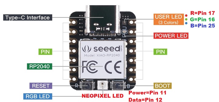
On-board LEDs
- Red Power LED
- USER LED (RGB)
- RED - P17
- board.LED_RED
- GRN - P16
- board.LED_GREEN
- LED_BUILTIN in Arduino
- BLU - P25
- board.LED_BLUE
- Code to Blink 3 LEDs
- RED - P17
- NEOPIXEL LED Features
- Individually addressable and programmable RGB LEDs
- Operating voltage: 3.3V to 5V
- Power consumption: 60mA per LED at full brightness
- Communication: PWM through data pin
- Driver IC: WS2812
- NEOPIXEL Power - P11 - set low for low power usage
- board.NEOPIXEL_POWER
- NEOPIXEL Data - P12
- board.NEOPIXEL
- NEOPIXEL Demo
Programming
- The RP2040 can be programmed in several languages/environments
- C/C++
- CircuitPython - best choice in most cases
- MicroPython
C/C++
- Can program in C/C++ using
- Arduino IDE
- Pico C++ SDK
C/C++ Adafruit RP2040 - Arduino
- Arduino IDE Setup
- Add the URL to the the Additional Boards Manager URLs
https://github.com/earlephilhower/arduino-pico/releases/download/global/package_rp2040_index.json
- Tools > Board > Boards Manager
- Search for RP2040
- Scroll down to the Raspberry Pi Pico/RP2040 by Earle F Philhower, III entry
- Click Install to install it
- Tools > Boards menu
- Navigate to the Raspberry Pi RP2040 Boards menu and choose Adafruit QT Py RP2040
C/C++ Seeeduino RP2040 - Arduino
- Arduino IDE Setup for Seeeduino RP2040 version
- Requires Arduino IDE version 1.8 or higher
- Add the URL to the the Additional Boards Manager URLs
https://files.seeedstudio.com/arduino/package_seeeduino_boards_index.json
C/C++ RP2040
CircuitPython
- CircuitPython is a derivative of MicroPython
- CircuitPython is the best choice in most use-cases
- Board specific support for both Seeed XAIO and Adafruit QT Py cards
- Welcome To CircuitPython - Adafruit tutorial
- Autorun code - CircuitPython looks for a code file on the board to run
- There are four options: code.txt, code.py, main.txt and main.py
- CircuitPython looks for those files, in that order, and then runs the first one it finds
- Mu code editor
CircuitPython for Adafruit QT Py RP2040
Install CircuitPython on Adafruit QT Py RP2040
- Adafruit CircuitPython Download page
- Running v7.3.0
- Hold down the BOOT (right) button while plugging it into USB
- Download UF2 from Adafruit QT Py CircuitPython RP2040
- Drive will open
- Drop UF2 onto drive
- Blink program
Updating CircuitPython on Adafruit QT Py RP2040
- Save the contents of CIRCUITPY, just in case
- Double-click the reset button to show the BOOT drive
- Drag the update-bootloader .uf2 file to the BOOT drive
- Wait a few tens of seconds for the bootloader to update; the BOOT drive will reappear
- Check INFO_UF2.TXT to verify that the bootloader version has been updated. Then you will need to reload CircuitPython.
- Update mpy files
CircuitPython for Seeed XIAO RP2040
- XIAO RP2040 with CircuitPython
- Our GitHub repo
- Use Thonny IDE
- Left click bottom right corner
- Select CircuitPython (generic)
- Left click bottom right corner
- Select Configure Interpreter
- Select USB Serial Device (COM<x)
- Pins list
import board
dir(board)
['__class__', '__name__', 'A0', 'A1', 'A2', 'A3', 'D0', 'D1', 'D10', 'D2', 'D3', 'D4', 'D5', 'D6', 'D7', 'D8', 'D9', 'I2C', 'LED', 'LED_BLUE', 'LED_GREEN', 'LED_RED', 'MISO', 'MOSI', 'NEOPIXEL', 'NEOPIXEL_POWER', 'RX', 'SCK', 'SCL', 'SDA', 'SPI', 'TX', 'UART', 'board_id']

>>> print(board.board_id)
seeeduino_xiao_rp2040
Install CircuitPython on Seeed XIAO RP2040
- Hold down the "BOOT" button. (The "B" is written on the board shown to the right)
- Connect the XIAO RP2040 to your computer while you still pressing the button.
- The computer then will appear a disk driver(RP1-RP2)
- Download the XIAO-RP2040-CircuitPython.uf2 file for XIAO RP2040
- Drag the .uf2 file to the disk driver("RP1-RP2")
- Check the disk drive if the name has changed to "CIRCUITPY" (takes a few seconds)
- Free memory
>>> import gc
>>> gc.mem_free()
208128
>>> import time
>>> gc.mem_free()
207952
CircuitPython Example Code
- i2cscan.py - Print list of I2C devices found
SSD1306 Display Examples
- ssd1306_TextFB.py - Displays 21 columns and 8 rows of text
- ssd1306_bouncing_ball.py - Bounce a ball
- ssd1306_framebuftest.py - Frame buffer demo
- ssd1306_simpletest_FB.py - Draws 3 pixels
Digital I/O Examples
Land Boards I2CIO-8 (MCP23008) Examples
- GitHub Repo
- I2CIO8.py Demo code - Bounce an LED across MCP23008 card output pins
- I2CIO8_RW.py - Read jumpers, write back LEDs
>>> dir(i2c)
['__class__', '__enter__', '__exit__', 'deinit', 'readfrom_into', 'scan', 'try_lock', 'unlock', 'writeto', 'writeto_then_readfrom']
Land Boards SWLEDX8-I2C (MCP23017) Examples
- SWLEDX8.py = Control the SWLEDX8-I2C card
Land Boards PROTO16-I2C (MCP23017) Examples
- PROTO16_Blink.py - Control the PROTO16-I2C card
MicroPython
MicroPython on XIAO RP2040
- XIAO RP2040 with MicroPython
- Software Setup
- Download and Install the latest version of Thonny editor according to your operating system
- Launch the Thonny IDE
- Click "Tools→Options" to open the settings.
- Step 4. Chose the "Interpreter" interface and select the device as "MicroPython(Raspberry Pi Pico)" and the port as "Try to detect prot automatically"
- Press and hold the "BOOT" button and then connect the XIAO RP2040 to the PC through the Type-C cable. If it works well, there is an "RPI-RP2" desk shown on the PC.
- Press the "Stop/Restart Backend" button and there will be a pop-up window that helps you install the MicroPython firmware on the board. The XIAO RP2040 uses the same chip as the Raspberry Pi Pico, thereby the XIAO RP2040 is compatible with Pico's MicroPython files.
- Write code (Neopixel example)
- Upload the codes by clicking the "Run current script" button. For the first time, Thonny will ask where you want to save your codes file. Both This Computer and Raspberry Pi Pico are fine.
MMBASIC on XIAO RP2040
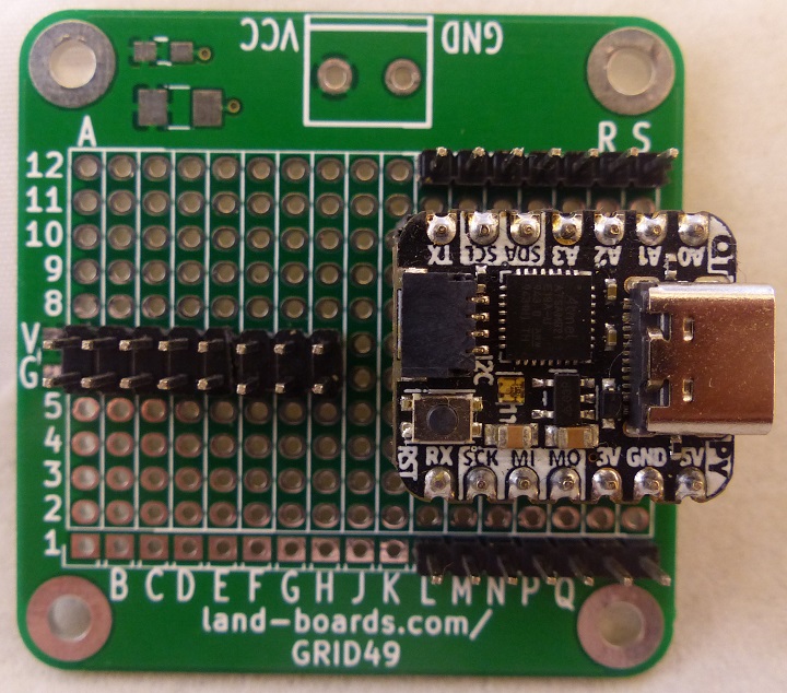
QT Py Breakout Board
- Built onto GRID49 card
- Socket for QT Py
- QT Py pins brought to header strips
- 3.3V power distribution on 2x8 header
Pins (CCW direction)
- S12 = A0
- R12 = A1
- Q12 = A2
- P12 = A3
- N12 = SDA
- M12 = SCL
- L12 = TX
- L1 = RX
- M1 = SCK
- N1 = MI
- P1 = MO
- Q1 = 3.3V
- R1 = GND
- S1 = 5V
- A6=B6=C6=D6=E6=F6=G6=H6 = GND
- A7=B7=C7=D7=E7=F7=G7=H7 = 3.3V
QTPy49 Board
Videos

