Difference between revisions of "RF Band Pass Filters"
Jump to navigation
Jump to search
Blwikiadmin (talk | contribs) |
|||
| (9 intermediate revisions by one other user not shown) | |||
| Line 1: | Line 1: | ||
== Description == | == Description == | ||
| − | + | * QRP Labe bandpass filter | |
| − | Strong signals that reach the receiver’s first mixer and/or RF pre-amplifier cross-modulate and produce | + | * Used at the front end of a receiver, to attenuate strong out-of-band signals |
| − | unwanted spurious responses at the receiver output. | + | * Strong signals that reach the receiver’s first mixer and/or RF pre-amplifier cross-modulate and produce unwanted spurious responses at the receiver output. |
| − | + | * Double-tuned circuit, among the most common filters found in radio equipment, consists of two tuned circuits, or resonators, that are coupled together, allowing energy in one to be shared with the other | |
| − | + | ** Designing a double-tuned circuit for use at HF and below is not difficult,' yet builders commonly encounter practical difficulties in building and adjusting the double-tuned circuit, especially at VHF and above | |
| + | ** The result may be a circuit that does not meet the filtering goal. | ||
== Design Details == | == Design Details == | ||
| Line 11: | Line 12: | ||
* Double-tuned circuit filter | * Double-tuned circuit filter | ||
* Based on [https://www.robkalmeijer.nl/techniek/electronica/radiotechniek/hambladen/qst/1991/12/page29/ The double-tuned Circuit: An experimenter's tutorial] | * Based on [https://www.robkalmeijer.nl/techniek/electronica/radiotechniek/hambladen/qst/1991/12/page29/ The double-tuned Circuit: An experimenter's tutorial] | ||
| − | + | * [https://qrp-labs.com/images/bpfkit/bpf2.pdf QRP Labs design] - Commercially available at reasonable cost | |
| + | * How to Create Band-pass Filter - [https://www.allaboutcircuits.com/textbook/alternating-current/chpt-8/band-pass-filters/ Design a Band-pass Filter Using Capacitors or Inductors] | ||
| + | |||
| + | [[file:bpf.jpg]] | ||
== Schematic == | == Schematic == | ||
| Line 22: | Line 26: | ||
== Performance (QRP Labs) == | == Performance (QRP Labs) == | ||
| + | |||
| + | * Insertion Loss | ||
| + | |||
| + | [[FILE:QRPLabs_BP_Filter_InsertionLoss.PNG]] | ||
* 20 MHz | * 20 MHz | ||
| Line 30: | Line 38: | ||
[[file:4_40m.jpg]] | [[file:4_40m.jpg]] | ||
| + | |||
| + | == QRP Labs Bandpass Filter == | ||
| + | |||
| + | * 20M - 14 MHz Filter | ||
| + | * NanoVNA | ||
| + | ** 12-16 MHz | ||
| + | |||
| + | [[FILE:14MHz_12-16MHz_Band_Pass_Filter-2.png]] | ||
| + | |||
| + | * Data | ||
| + | |||
| + | [[FILE:14MHz_12-16MHz_Band_Pass_Filter-Data.png]] | ||
| + | |||
| + | [[FILE: 14MHz_12-16MHz_Band_Pass_Filter-Analysis.png]] | ||
Latest revision as of 12:42, 31 May 2023
Contents
Description
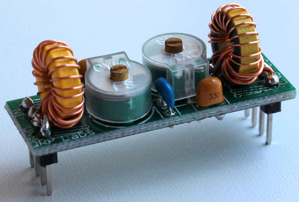
- QRP Labe bandpass filter
- Used at the front end of a receiver, to attenuate strong out-of-band signals
- Strong signals that reach the receiver’s first mixer and/or RF pre-amplifier cross-modulate and produce unwanted spurious responses at the receiver output.
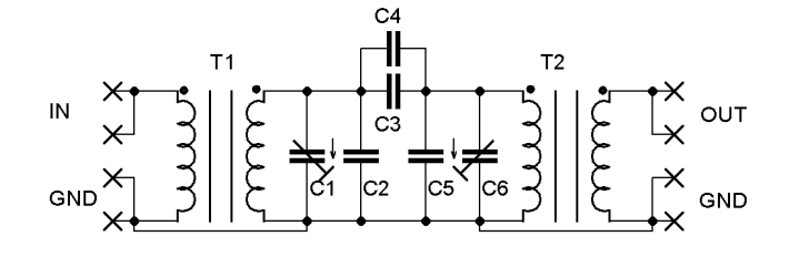
- Double-tuned circuit, among the most common filters found in radio equipment, consists of two tuned circuits, or resonators, that are coupled together, allowing energy in one to be shared with the other
- Designing a double-tuned circuit for use at HF and below is not difficult,' yet builders commonly encounter practical difficulties in building and adjusting the double-tuned circuit, especially at VHF and above
- The result may be a circuit that does not meet the filtering goal.
Design Details
- Double-tuned circuit filter
- Based on The double-tuned Circuit: An experimenter's tutorial
- QRP Labs design - Commercially available at reasonable cost
- How to Create Band-pass Filter - Design a Band-pass Filter Using Capacitors or Inductors
Schematic
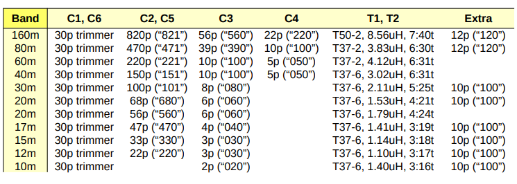
Parts
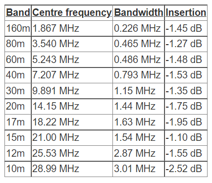
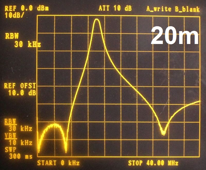
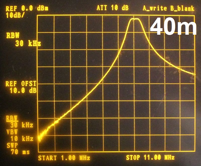
Performance (QRP Labs)
- Insertion Loss
- 20 MHz
- 40 MHz
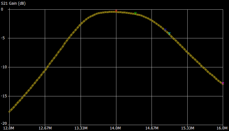
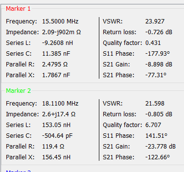
QRP Labs Bandpass Filter
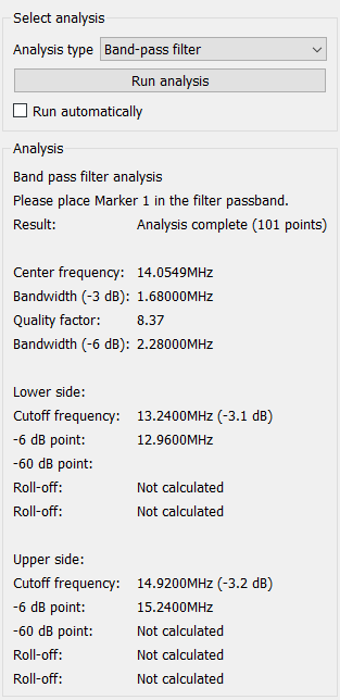
- 20M - 14 MHz Filter
- NanoVNA
- 12-16 MHz
- Data
