Difference between revisions of "RPI PSOC5"
Jump to navigation
Jump to search
Blwikiadmin (talk | contribs) |
Blwikiadmin (talk | contribs) |
||
| Line 111: | Line 111: | ||
** 4 pin 1:1 Dupont cable | ** 4 pin 1:1 Dupont cable | ||
** USB A Male to female cable | ** USB A Male to female cable | ||
| + | |||
| + | [[file:LitProgPlusCable_6159.jpg]] | ||
| + | |||
* Has a CY8C5868LTI-LP039 used as the programmer | * Has a CY8C5868LTI-LP039 used as the programmer | ||
* [https://www.infineon.com/dgdl/Infineon-CY8CKIT-059_PSoC_5LP_Prototyping_Kit_Guide-UserManual-v01_00-EN.pdf CY8CKIT-059 Guide] | * [https://www.infineon.com/dgdl/Infineon-CY8CKIT-059_PSoC_5LP_Prototyping_Kit_Guide-UserManual-v01_00-EN.pdf CY8CKIT-059 Guide] | ||
| Line 116: | Line 119: | ||
* Sometimes need to press "BOOT/TARGET RESET" SW3 pushbutton for -6 seconds until PC detects and drive comes up on PC | * Sometimes need to press "BOOT/TARGET RESET" SW3 pushbutton for -6 seconds until PC detects and drive comes up on PC | ||
| − | [[ | + | [[FILE:KITPROG_RST.png]] |
* Program using [https://www.infineon.com/cms/en/design-support/tools/sdk/psoc-software/psoc-creator/ PSOC Creator] | * Program using [https://www.infineon.com/cms/en/design-support/tools/sdk/psoc-software/psoc-creator/ PSOC Creator] | ||
Revision as of 17:14, 5 April 2022
Contents
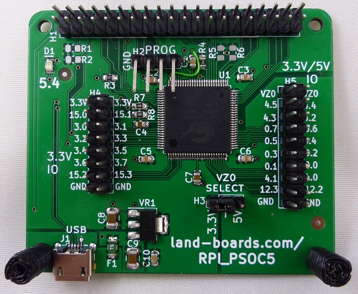
Raspberry Pi Clone
Features
- Raspberry Pi Electrical and Mechanical Compatible
- 40 pin GPIO connector
- Connects to all GPIO pins of the Raspberry Pi
- Programmable System on a Chip (PSoC)
- Cypress Semiconductor
- USB Micro connector
- Placed in the same location as a Raspberry Pi
- Provides 5V power
- 5V power is polyfuse protected
- 3.3V regulator
- 3.3V or 5V I/O
- H3 - Voltage Select Jumper
- On-board LED
- PSOC Pin 5.4
Connectors
J1 - USB Power Connector
- USB Micro B
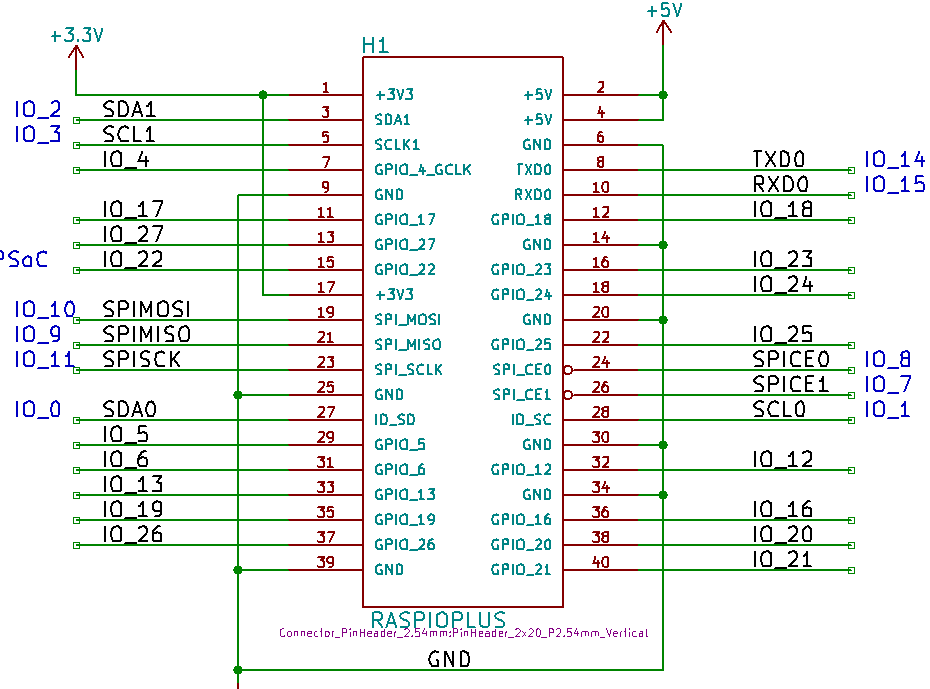
H1 - 40 Pin GPIO Connector
- BCM pin numbers
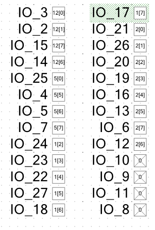
- PSOC5 to BCM mapping
H2 - Programming header
- GND
- RESET*
- SWDCK
- SWDIO
H3 - Power Select connector
- 1-2 = 3.3V
- 2-3 = 5V
H4 - 3.3V GPIO connector
- 3.3V
- 3.3V
- 15.0
- 15.1
- 3.0
- 3.1
- 3.2
- 3.3
- 3.4
- 3.5
- 3.6
- 3.7
- 15.2
- 15.3
- GND
- GND
H5 = 3.3V or 5V GPIO connector
- VZ0
- VZ0
- 4.5
- 4.4
- 4.3
- 4.2
- 0.7
- 0.6
- 0.5
- 0.4
- 0.3
- 0.2
- 0.1
- 0.0
- 4.1
- 4.0
- 12.3
- 12.2
- GND
- GND
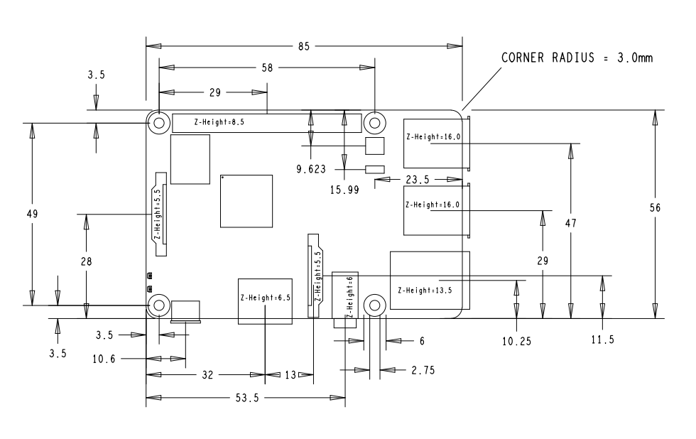
Raspberry Pi Mechanicals
Drivers/Source Code
Schematic
Programming
- KitProg is a part of CY8CKIT-059
- Fitted with 1x4 right angle header
- Programming cable
- 4 pin 1:1 Dupont cable
- USB A Male to female cable
- Has a CY8C5868LTI-LP039 used as the programmer
- CY8CKIT-059 Guide
- KitProg User Manual
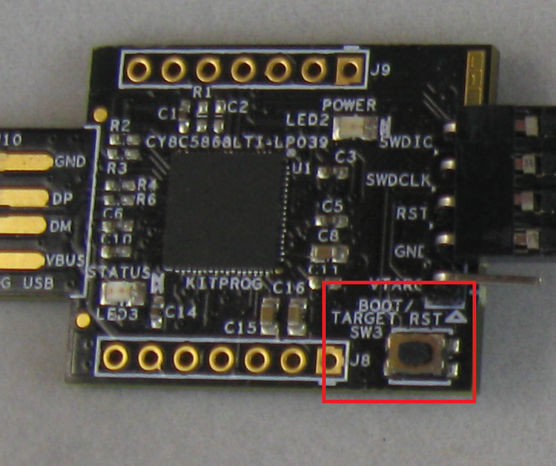
- Sometimes need to press "BOOT/TARGET RESET" SW3 pushbutton for -6 seconds until PC detects and drive comes up on PC
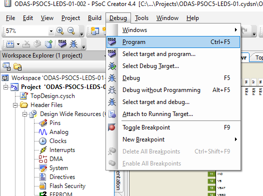
- Program using PSOC Creator
- Select Debug, Program
- Select Device/connect
Factory Acceptance Test
- Raspberry Pi Test Station - Tests itself
Equipment
- Unit Under Test
- RPI_PSOC5
- Host computer
- Connected via Micro-USB cable
- Running PuTTY
- 115,200 baud
- LED-32 - LED Test Card
- Cable set from UUT to LED-32
- Load UUT card with RPI_PSOC5_Serial_01 test software
