Difference between revisions of "SD Loader"
Blwikiadmin (talk | contribs) |
Blwikiadmin (talk | contribs) |
||
| (149 intermediate revisions by the same user not shown) | |||
| Line 1: | Line 1: | ||
| − | + | [[file:SDLoader_QTPy49-01_P18543-720px.jpg]] | |
| − | + | <video type="youtube">iI9lUsVSuF8</video> | |
| − | + | ||
| + | == Introduction == | ||
| + | |||
| + | Legacy computer systems typically load and save programs over serial ports. This is often done by attaching a PC and running a terminal program to send/receive programs to the legacy systems. Integrating modern storage, like SD cards, can be a serious challenge into legacy designs. | ||
| + | |||
| + | Replacing the external PC offers the opportunity to more easily transport the system. A compact solution that emulates the PC for transfers would be useful. | ||
| + | |||
| + | This design transfers files to/from an SD card via a serial port. It runs a menu driven program on small OLED to control transfers and supports SD cards up to 32GB (FAT32 formatted). The serial interface has RTS/CTS hardware handshake support. It can run with 5V or 3.3V target systems or at RS-232 levels. Custom cards could easily be added to emulate cassette interfaces or run. | ||
| + | |||
| + | [https://hackaday.io/project/185744-sdserial-card-loader Hackaday page] | ||
== Features == | == Features == | ||
| Line 14: | Line 23: | ||
* Constructed out of existing Land Boards cards | * Constructed out of existing Land Boards cards | ||
| − | * [[ | + | * [[QT_Py#RP2040_QT_Py|RP2040 board]] versions |
| − | * [[ | + | ** [[QT_Py#SAMD21_QT_Py|SAMD board]] does not have enough SRAM to use CircuitPython, needs Arduino IDE |
| + | ** [[QT_Py#RP2040_QT_Py|RP2040 board]] has a lot more SRAM and is easier to program for directory lists | ||
| + | ** [[QTPy49-01]] QT Py or XIAO RP2040 Adapter card | ||
* [[MyMenu]] | * [[MyMenu]] | ||
** MCP23008 I2C interface | ** MCP23008 I2C interface | ||
** OLED | ** OLED | ||
| − | ** 5 | + | ** 5 Pushbuttons |
** 3 LEDs | ** 3 LEDs | ||
| − | * Level Shifter mounted on [[GRID49]] card | + | * Optional [[DCE]] or [[DTE]] RS-232 Level Translator card |
| + | * Optional Level Shifter mounted on [[GRID49]] card | ||
| + | ** Used for legacy 5V system targets | ||
| + | * Optional [[Mini360 Adapter Board]] | ||
| + | ** Wide-range input Power card (7-23V) | ||
| + | |||
| + | === QTPy49-01 Card === | ||
| − | + | * Easier to cable external cards | |
| + | * SD Card socket | ||
| + | * Flexible power (7-12V) | ||
| − | [[ | + | [[file:QTPy49-01-P1080524-720px.jpg]] |
| − | === | + | === MyMenu === |
| − | + | * I2C interface to OLED, I2C Port Expander with 3 LEDs, 5 switches | |
| − | === | + | [[file:MyMenu-CCA-X3_5793-800px.jpg]] |
| + | |||
| + | [http://ww1.microchip.com/downloads/en/DeviceDoc/21919e.pdf MCP23008 Data Sheet] | ||
| + | <pre> | ||
| + | GPIO Port Map | ||
| + | GP0 - LED D3 | ||
| + | GP1 - LED D2 | ||
| + | GP2 - LED D1 | ||
| + | GP3 - Select button 0 = pressed | ||
| + | GP4 - Right button | ||
| + | GP5 - Down button | ||
| + | GP6 - Up button | ||
| + | GP7 - Left button | ||
| + | </pre> | ||
| + | |||
| + | === DTE - RS-232 to TTL Level Shifter (Optional) === | ||
| + | |||
| + | [[file:DTE_P562-720px.jpg]] | ||
| + | |||
| + | * The DTE (PC) has the male DB-9 connector | ||
| + | |||
| + | [[File:DTE_DCE.png]] | ||
| + | |||
| + | === 5V Level Shifter (Optional) === | ||
| − | [[ | + | * Use for "legacy" 5V Serial target systems |
| + | ** Not used for 3.3V systems | ||
| + | * Convert 3.3V QT Py Tx/Rx/RTS/CTS to "legacy" 5V | ||
| + | * Isolated 3.3V/5V power | ||
| + | * Common Ground | ||
| + | * Built on [[GRID49]] card | ||
| + | * [https://www.adafruit.com/product/757 Adafruit 4-channel I2C-safe Bi-directional Logic Level Converter] | ||
| + | * [[SH-LEV-01]] - New | ||
| − | + | [[file:LVL_SH_P18228-720px.jpg]] | |
| − | + | == QTPy49-01 Card Cabling == | |
| − | |||
| − | [[file: | + | [[file:QTPy49-P18253-720pxV.jpg]] |
| − | [[ | + | * [[QTPy49-01]] Card has function specific headers |
| − | + | [[file:QTPy49-01_SD_Loader.PNG]] | |
| − | === | + | === QTPy49-01 Card to MyMenu Cabling === |
{| class="wikitable" | {| class="wikitable" | ||
| − | ! | + | ! QTPy49 |
! SIGNAL | ! SIGNAL | ||
| − | ! | + | ! MyMenu |
! COLOR | ! COLOR | ||
|- | |- | ||
| − | | | + | | J5-1 |
| − | | | + | | GND |
| − | | | + | | P2-1 |
| + | | BLK | ||
| + | |- | ||
| + | | J5-2 | ||
| + | | +3.3V | ||
| + | | P2-2 | ||
| + | | RED | ||
| + | |- | ||
| + | | J5-3 | ||
| + | | SDA | ||
| + | | P2-3 | ||
| + | | WHT | ||
| + | |- | ||
| + | | J5-4 | ||
| + | | SCL | ||
| + | | P2-4 | ||
| BRN | | BRN | ||
|- | |- | ||
| − | | D1 | + | |} |
| − | | | + | |
| − | | | + | === QTPy49 Card to Host Serial === |
| + | |||
| + | {| class="wikitable" | ||
| + | ! QTPy49 | ||
| + | ! SIGNAL | ||
| + | ! COLOR | ||
| + | |- | ||
| + | | J8-3 (D1) | ||
| + | | RTS* (in) | ||
| + | | GRY | ||
| + | |- | ||
| + | | J7-1 (D2) | ||
| + | | CTS* (out) | ||
| ORA | | ORA | ||
|- | |- | ||
| − | | | + | | J4-4 (RX) |
| − | + | | RX | |
| − | | | + | | BRN |
| − | | | ||
|- | |- | ||
| − | | | + | | J4-3 (TX) |
| − | + | | TX | |
| − | | | ||
| WHT | | WHT | ||
|- | |- | ||
| − | | | + | | J4-2 (VCC) |
| − | | + | + | | +3.3V |
| − | + | | Xlator (only) | |
| − | | | ||
|- | |- | ||
| + | | J4-1 (GND) | ||
| GND | | GND | ||
| − | |||
| − | |||
| BLK | | BLK | ||
|- | |- | ||
|} | |} | ||
| − | === | + | == QT Py Breakout Card (Alternate) == |
| + | |||
| + | * Do not install 5mm Terminal Block | ||
| + | |||
| + | [[File:QT_Py_Breakout_P18212-720px.jpg]] | ||
| + | |||
| + | * Power via USB C cable | ||
| + | |||
| + | == QT Py Breakout Card (on GRID49 card) Cabling == | ||
| + | |||
| + | * [[GRID49]] card | ||
| + | * QT Py uses (2) 1x7 male headers for signals | ||
| + | ** Cut off 1 set of holes of (2) female housings to make 1x7 female headers | ||
| + | * SD Card uses (1) 1x8 header | ||
| + | * MyMenu uses (1) 1x5 header | ||
| + | * QT Py uses 2x8 header for 3.3V and Ground | ||
| + | ** Use 2x3 female housings | ||
| + | * 40mm cables to Host Target | ||
| + | |||
| + | [[file:SD_Loader_App_Schematic.PNG]] | ||
| + | |||
| + | === QT Py Breakout Card Cabling === | ||
{| class="wikitable" | {| class="wikitable" | ||
| − | ! | + | ! QT Py |
! SIGNAL | ! SIGNAL | ||
| − | ! | + | ! CARD |
| + | ! PIN | ||
! COLOR | ! COLOR | ||
|- | |- | ||
| − | | | + | | 01 (AD0) |
| − | | | + | | INT(AD0) |
| − | | | + | | MyMenu |
| − | | | + | | P2-5 |
| + | | GRY | ||
| + | |- | ||
| + | | 02 (AD1) | ||
| + | | RTS* | ||
| + | | TARGET | ||
| + | | TBD | ||
| + | | GRY | ||
| + | |- | ||
| + | | 03 (AD2) | ||
| + | | CTS* | ||
| + | | TARGET | ||
| + | | TBD | ||
| + | | ORA | ||
|- | |- | ||
| − | | | + | | 04 (AD3) |
| − | | | + | | SS* |
| − | | | + | | SD_CARD |
| − | | | + | | J1-5 |
| + | | GRY | ||
|- | |- | ||
| − | | | + | | 05 (SDA) |
| SDA | | SDA | ||
| + | | MyMenu | ||
| P2-3 | | P2-3 | ||
| WHT | | WHT | ||
|- | |- | ||
| − | | | + | | 06 (SCL) |
| SCL | | SCL | ||
| + | | MyMenu | ||
| P2-4 | | P2-4 | ||
| BRN | | BRN | ||
|- | |- | ||
| − | | | + | | 07 (TX) |
| − | | | + | | TX |
| − | | | + | | TARGET |
| − | | | + | | TBD |
| + | | WHT | ||
| + | |- | ||
| + | | 08 (RX) | ||
| + | | RX | ||
| + | | TARGET | ||
| + | | TBD | ||
| + | | BRN | ||
|- | |- | ||
| − | | | + | | 09 (SCK) |
| − | + | | SCK | |
| − | + | | SD_CARD | |
| − | + | | J1-3 | |
| − | + | | BLU | |
| − | |||
| − | |||
| − | |||
| − | |||
|- | |- | ||
| − | | | + | | 10 (MI) |
| − | | | + | | MISO |
| + | | SD_CARD | ||
| J1-2 | | J1-2 | ||
| BRN | | BRN | ||
|- | |- | ||
| − | | | + | | 11 (MO) |
| − | | +5V | + | | MOSI |
| + | | SD_CARD | ||
| + | | J1-4 | ||
| + | | WHT | ||
| + | |- | ||
| + | | 12 (3V) | ||
| + | | +3.3V | ||
| + | | GRID49 | ||
| + | | Q7 | ||
| + | | WIRE | ||
| + | |- | ||
| + | | 13 (GND) | ||
| + | | GND | ||
| + | | GRID49 | ||
| + | | R7 | ||
| + | | WIRE | ||
| + | |- | ||
| + | | 14 (5V) | ||
| + | | 5V | ||
| + | | N/C | ||
| + | | | ||
| + | | | ||
| + | |- | ||
| + | | PWR-01 | ||
| + | | +3.3V | ||
| + | | SD_CARD | ||
| J1-8 | | J1-8 | ||
| RED | | RED | ||
|- | |- | ||
| − | | | + | | PWR-02 |
| − | | | + | | +3.3V |
| − | | | + | | TARGET |
| − | | | + | | TBD |
| + | | RED | ||
|- | |- | ||
| − | | | + | | PWR-03 |
| − | | | + | | +3.3V |
| − | | | + | | MyMenu |
| − | | | + | | P2-2 |
| + | | RED | ||
|- | |- | ||
| − | | | + | | PWR-14 |
| − | | | + | | GND |
| − | | | + | | MyMenu |
| − | | | + | | P2-1 |
| + | | BLK | ||
|- | |- | ||
| − | | | + | | PWR-15 |
| GND | | GND | ||
| + | | SD_CARD | ||
| J1-1 | | J1-1 | ||
| BLK | | BLK | ||
|- | |- | ||
| − | | | + | | PWR-16 |
| − | | | + | | GND |
| − | | | + | | TARGET |
| − | | | + | | TBD |
| + | | BLK | ||
|- | |- | ||
|} | |} | ||
| − | == Software == | + | == Arduino Software == |
| + | |||
| + | * i2cscan of attached cards shows OLED at 0x3c and MCP23008 at 0x20 | ||
| + | <pre> | ||
| + | I2C addresses found: ['0x20', '0x3c'] | ||
| + | </pre> | ||
| + | |||
| + | === Arduino Software Development Environment === | ||
| − | * | + | * Developed using Arduino IDE V1.8.xx |
| + | * [https://learn.adafruit.com/adafruit-qt-py/arduino-ide-setup Arduino IDE Setup for QT Py] | ||
| + | * Requires Arduino IDE version 1.8 or higher | ||
| + | * Add to Preferences Additional Boards Manager URLs | ||
| + | <pre> | ||
| + | https://adafruit.github.io/arduino-board-index/package_adafruit_index.json | ||
| + | |||
| + | </pre> | ||
| + | * [https://learn.adafruit.com/adafruit-qt-py/using-with-arduino-ide Add Adafruit SAMD Boards in Boards Manager] | ||
| + | * [https://learn.adafruit.com/adafruit-qt-py/adapting-sketches-to-m0-m4 Adapting Sketches to M0 & M4] | ||
| + | ** Specifics | ||
| + | <pre> | ||
| + | pinMode(pin, INPUT_PULLUP) | ||
| − | === Human Interface Design (HID) === | + | #if defined(ARDUINO_SAMD_ZERO) && defined(SERIAL_PORT_USBVIRTUAL) |
| + | // Required for Serial on Zero based boards | ||
| + | #define Serial SERIAL_PORT_USBVIRTUAL | ||
| + | #endif | ||
| + | |||
| + | const char str[] = "My very long string"; | ||
| + | </pre> | ||
| + | * [https://learn.adafruit.com/adafruit-qt-py/uf2-bootloader-details UF2 Bootloader Details] | ||
| + | |||
| + | === Arduino Human Interface Design (HID) === | ||
* Menu driven | * Menu driven | ||
| Line 177: | Line 348: | ||
** [https://github.com/olikraus/u8g2/wiki/u8x8reference ug2 u8x8 OLED display driver software] | ** [https://github.com/olikraus/u8g2/wiki/u8x8reference ug2 u8x8 OLED display driver software] | ||
| − | === SD Card === | + | === Arduino SD Card === |
| + | |||
| + | * Library | ||
| + | * Example files | ||
| + | |||
| + | ==== Arduino SD Card Library ==== | ||
* [https://www.arduino.cc/reference/en/libraries/sd/ SD Card library] | * [https://www.arduino.cc/reference/en/libraries/sd/ SD Card library] | ||
** The SD library allows for reading from and writing to SD cards, e.g. on the Arduino Ethernet Shield | ** The SD library allows for reading from and writing to SD cards, e.g. on the Arduino Ethernet Shield | ||
| − | ** | + | ** Based on [https://github.com/greiman/SdFat sdfatlib] |
** The library supports FAT16 and FAT32 file systems on standard SD cards and SDHC cards | ** The library supports FAT16 and FAT32 file systems on standard SD cards and SDHC cards | ||
** It uses short 8.3 names for files | ** It uses short 8.3 names for files | ||
| Line 190: | Line 366: | ||
** Additionally, another pin must be used to select the SD card | ** Additionally, another pin must be used to select the SD card | ||
** This can be the hardware SS pin - pin 10 (on most Arduino boards) or pin 53 (on the Mega) - or another pin specified in the call to SD.begin() | ** This can be the hardware SS pin - pin 10 (on most Arduino boards) or pin 53 (on the Mega) - or another pin specified in the call to SD.begin() | ||
| − | |||
| − | + | ==== Arduino SD Card Example Code ==== | |
| − | + | ||
| − | + | * [https://docs.arduino.cc/learn/programming/sd-guide SD Card example Code] | |
| − | + | * [https://github.com/land-boards/lb-Arduino-Code/tree/master/LBCards/SDCard/RW_File Read and Write File example] | |
| − | + | * [https://github.com/land-boards/lb-Arduino-Code/tree/master/LBCards/SDCard/CardInfo Read Card Information] | |
| − | + | * [https://github.com/land-boards/lb-Arduino-Code/tree/master/LBCards/SDCard/DumpFile Read a file from a SD card using the SD library and send it over the serial port] | |
| + | * [https://github.com/land-boards/lb-Arduino-Code/tree/master/LBCards/SDCard/CreateDeleteFile Create and destroy a file on a SD card] | ||
| + | * [https://github.com/land-boards/lb-Arduino-Code/tree/master/LBCards/SDCard/SD_Dir List the files available in the directory of the SD card] | ||
| + | |||
| + | ==== Arduino SD Card Connections ==== | ||
| + | |||
| + | * Uses default board SPI pins | ||
| + | * Uses D3 as chip select | ||
=== Serial === | === Serial === | ||
| Line 207: | Line 389: | ||
** This is data that’s already arrived and stored in the serial receive buffer (which holds 64 bytes). | ** This is data that’s already arrived and stored in the serial receive buffer (which holds 64 bytes). | ||
** Turn off/on receive handshake based on Serial.available() count and storage | ** Turn off/on receive handshake based on Serial.available() count and storage | ||
| + | * [https://www.arduino.cc/reference/en/language/functions/communication/serial/write/ Serial.write()] | ||
| + | ** Writes binary data to the serial port | ||
| + | ** This data is sent as a byte or series of bytes | ||
| + | ** To send the characters representing the digits of a number use the print() function instead. | ||
| + | ** Syntax | ||
| − | === References === | + | <pre> |
| + | Serial.write(val) | ||
| + | Serial.write(str) | ||
| + | Serial.write(buf, len) | ||
| + | </pre> | ||
| + | |||
| + | == CircuitPython Software == | ||
| + | |||
| + | * CircuitPython has several advantages over Arduino IDE | ||
| + | ** Build-test-built cycle time much faster | ||
| + | ** '''Much easier to do list processing for directory structure''' | ||
| + | ** Speed not critical in this application | ||
| + | * Not enough SRAM with SAMD version of the card | ||
| + | ** RP2040 version of the card has plenty of SRAM | ||
| + | ** [https://www.seeedstudio.com/XIAO-RP2040-v1-0-p-5026.html XAIO RP2040] is $5.40 and ships quickly from US Warehouse | ||
| + | |||
| + | === CircuitPython Software Development Environment === | ||
| + | |||
| + | * [https://github.com/land-boards/QT-Py/tree/main/CircuitPython CircuitPython repo] | ||
| + | * [https://github.com/land-boards/QT-Py/tree/main/CircuitPython/lbcards/SDLoader SDLoader GitHub repo] | ||
| + | * Use [https://thonny.org/ Thonny IDE] | ||
| + | ** Left click bottom right corner | ||
| + | ** Select CircuitPython (generic) | ||
| + | ** Left click bottom right corner | ||
| + | ** Select Configure Interpreter | ||
| + | ** Select USB Serial Device (COM<x) | ||
| + | * Pins list | ||
| + | |||
| + | <pre> | ||
| + | import board | ||
| + | dir(board) | ||
| + | ['__class__', '__name__', 'A0', 'A1', 'A2', 'A3', 'D0', 'D1', 'D10', 'D2', 'D3', 'D4', 'D5', 'D6', 'D7', 'D8', 'D9', 'I2C', 'LED', 'LED_BLUE', 'LED_GREEN', 'LED_RED', 'MISO', 'MOSI', 'NEOPIXEL', 'NEOPIXEL_POWER', 'RX', 'SCK', 'SCL', 'SDA', 'SPI', 'TX', 'UART', 'board_id'] | ||
| + | |||
| + | >>> print(board.board_id) | ||
| + | seeeduino_xiao_rp2040 | ||
| + | </pre> | ||
| + | |||
| + | ==== Install CircuitPython on Seeed XIAO RP2040 ==== | ||
| + | |||
| + | * Long press the "BOOT" button. (The "B" is written on the board shown to the right) | ||
| + | * Connect the XIAO PR2040 to your computer while you still pressing the button. | ||
| + | * The computer then will appear a disk driver(RP1-RP2) | ||
| + | * Download the [https://files.seeedstudio.com/wiki/XIAO-RP2040/res/XIAO-RP2040-CircuitPython.uf2 XIAO-RP2040-CircuitPython.uf2 file] for XIAO RP2040 | ||
| + | * Drag the .uf2 file to the disk driver("RP1-RP2") | ||
| + | * Check the disk drive if the name has changed to "CIRCUITPY" (takes a few seconds) | ||
| + | * Free memory | ||
| + | |||
| + | <pre> | ||
| + | >>> import gc | ||
| + | >>> gc.mem_free() | ||
| + | 208128 | ||
| + | >>> import time | ||
| + | >>> gc.mem_free() | ||
| + | 207952 | ||
| + | </pre> | ||
| + | |||
| + | === CircuitPython Human Interface Design (HID) === | ||
| + | |||
| + | * [[MyMenu]] card | ||
| + | ** 0.91" OLED | ||
| + | ** 3 LEDs | ||
| + | ** 5 pushbuttons | ||
| + | * [https://github.com/land-boards/QT-Py/blob/main/CircuitPython/Seeed_XIAO_RP2040/i2cscan.py i2cscan] of attached cards shows OLED at 0x3c and MCP23008 at 0x21 | ||
| + | * Added i2cscan code to find the MCP23008 on the [[MyMenu]] card | ||
| + | * [https://github.com/land-boards/QT-Py/blob/main/CircuitPython/Seeed_XIAO_RP2040/MyMenu.py MyMenu demo/test code] | ||
| + | ** Read pushbuttons | ||
| + | ** Write OLED | ||
| + | ** Write LEDs | ||
| + | ** Exit by pressing Select button | ||
| + | |||
| + | === CircuitPython SD Card === | ||
| + | |||
| + | * [https://docs.circuitpython.org/en/latest/shared-bindings/sdcardio/index.html SD card module reference] | ||
| + | * [https://docs.circuitpython.org/en/latest/shared-bindings/storage/index.html#module-storage storage module reference] | ||
| + | * [https://learn.adafruit.com/adafruit-microsd-spi-sdio/using-sdcardio Using sdcardio] | ||
| + | * [https://learn.adafruit.com/adafruit-microsd-spi-sdio/example-listing-files-on-sd-card Listing files on SD card] | ||
| + | * sdcardio class constructor | ||
| + | <pre> | ||
| + | sdcardio.SDCard(bus: busio.SPI, cs: microcontroller.Pin, baudrate: int = 8000000) | ||
| + | </pre> | ||
| + | |||
| + | ==== Example code ==== | ||
| + | |||
| + | * [https://github.com/land-boards/QT-Py/blob/main/CircuitPython/Seeed_XIAO_RP2040/SDCard_ListDir.py Initialize SD card and read directory] | ||
| + | * Result | ||
| + | <pre> | ||
| + | >>> %Run -c $EDITOR_CONTENT | ||
| + | Files on filesystem: | ||
| + | ==================== | ||
| + | System Volume Information/ Size: 0 by | ||
| + | WPSettings.dat Size: 12 by | ||
| + | IndexerVolumeGuid Size: 76 by | ||
| + | SuperStarTrek.bas Size: 20.0 KB | ||
| + | scramble.bas Size: 19.2 KB | ||
| + | CivilWar.bas Size: 13.5 KB | ||
| + | >>> | ||
| + | </pre> | ||
| + | * Storing path, file name as set pairs, gives | ||
| + | <pre> | ||
| + | dirFileNames [('/sd', 'System Volume Information'), ('/sd/System Volume Information', 'WPSettings.dat'), ('/sd/System Volume Information', 'IndexerVolumeGuid'), ('/sd', 'SuperStarTrek.bas'), ('/sd', 'scramble.bas'), ('/sd', 'CivilWar.bas')] | ||
| + | ('/sd', 'System Volume Information') | ||
| + | ('/sd/System Volume Information', 'WPSettings.dat') | ||
| + | ('/sd/System Volume Information', 'IndexerVolumeGuid') | ||
| + | ('/sd', 'SuperStarTrek.bas') | ||
| + | ('/sd', 'scramble.bas') | ||
| + | ('/sd', 'CivilWar.bas') | ||
| + | </pre> | ||
| + | |||
| + | === CircuitPython Serial === | ||
| + | |||
| + | * [https://docs.circuitpython.org/en/latest/shared-bindings/busio/#busio.UART busio UART reference] | ||
| + | * Supports RTS/CTS | ||
| + | ** [https://docs.micropython.org/en/v1.9.3/pyboard/library/pyb.UART.html#flow-control MicroPython UART flow control] | ||
| + | * Constructor | ||
| + | <pre> | ||
| + | lassbusio.UART(tx: microcontroller.Pin, rx: microcontroller.Pin, *, baudrate: int = 9600, bits: int = 8, parity: Optional[Parity] = None, stop: int = 1, timeout: float = 1, receiver_buffer_size: int = 64) | ||
| + | </pre> | ||
| + | * RTS, CTS pins defines on QT Py RP2040 | ||
| + | ** RTS = pin D2 | ||
| + | ** CTS = pin D3 | ||
| + | ` | ||
| + | ==== Serial Protocol References ==== | ||
* [https://www.geeksforgeeks.org/xmodem-file-transfer-protocol/ XMODEM Protocol] | * [https://www.geeksforgeeks.org/xmodem-file-transfer-protocol/ XMODEM Protocol] | ||
* [https://en.wikipedia.org/wiki/SREC_(file_format)#Record_structure S record format] | * [https://en.wikipedia.org/wiki/SREC_(file_format)#Record_structure S record format] | ||
Latest revision as of 08:25, 20 August 2022
Contents
Introduction
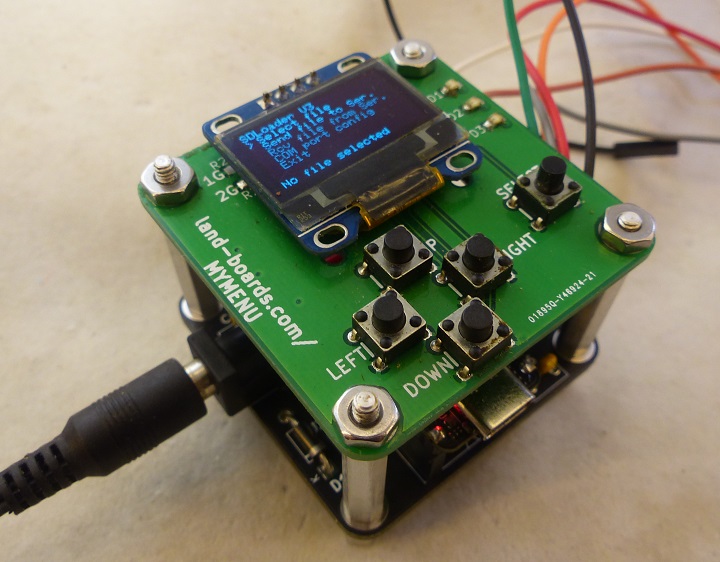
Legacy computer systems typically load and save programs over serial ports. This is often done by attaching a PC and running a terminal program to send/receive programs to the legacy systems. Integrating modern storage, like SD cards, can be a serious challenge into legacy designs.
Replacing the external PC offers the opportunity to more easily transport the system. A compact solution that emulates the PC for transfers would be useful.
This design transfers files to/from an SD card via a serial port. It runs a menu driven program on small OLED to control transfers and supports SD cards up to 32GB (FAT32 formatted). The serial interface has RTS/CTS hardware handshake support. It can run with 5V or 3.3V target systems or at RS-232 levels. Custom cards could easily be added to emulate cassette interfaces or run.
Features
- Supports SD cards up to 32GB
- FAT32 formatted
- Serial interface
- Full hardware Handshake support
Cards
- Constructed out of existing Land Boards cards
- RP2040 board versions
- SAMD board does not have enough SRAM to use CircuitPython, needs Arduino IDE
- RP2040 board has a lot more SRAM and is easier to program for directory lists
- QTPy49-01 QT Py or XIAO RP2040 Adapter card
- MyMenu
- MCP23008 I2C interface
- OLED
- 5 Pushbuttons
- 3 LEDs
- Optional DCE or DTE RS-232 Level Translator card
- Optional Level Shifter mounted on GRID49 card
- Used for legacy 5V system targets
- Optional Mini360 Adapter Board
- Wide-range input Power card (7-23V)
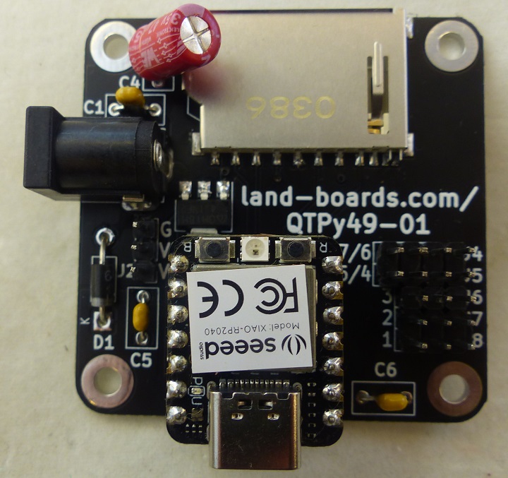
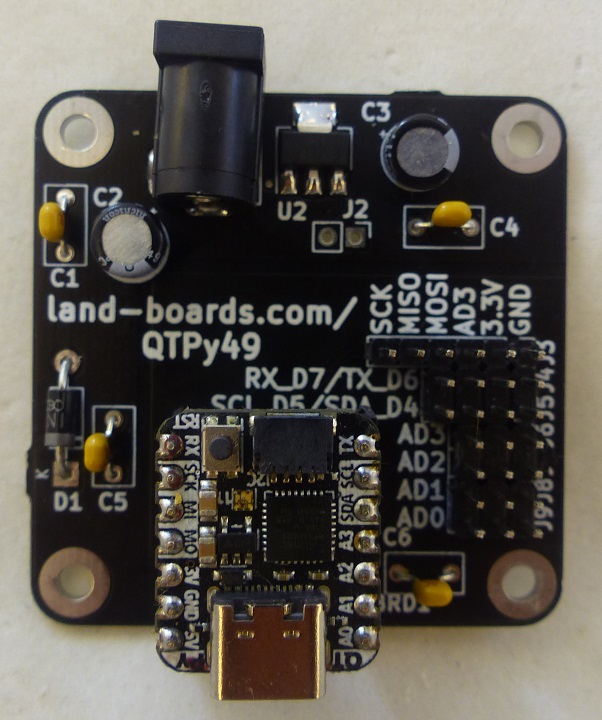
QTPy49-01 Card
- Easier to cable external cards
- SD Card socket
- Flexible power (7-12V)
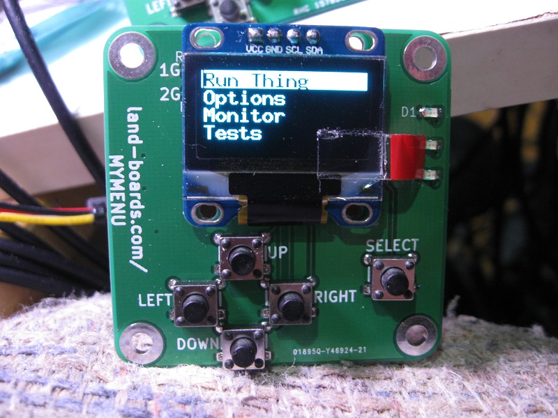
MyMenu
- I2C interface to OLED, I2C Port Expander with 3 LEDs, 5 switches
GPIO Port Map
GP0 - LED D3
GP1 - LED D2
GP2 - LED D1
GP3 - Select button 0 = pressed
GP4 - Right button
GP5 - Down button
GP6 - Up button
GP7 - Left button
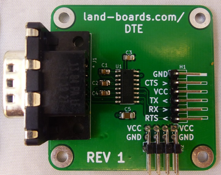
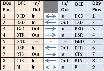
DTE - RS-232 to TTL Level Shifter (Optional)
- The DTE (PC) has the male DB-9 connector
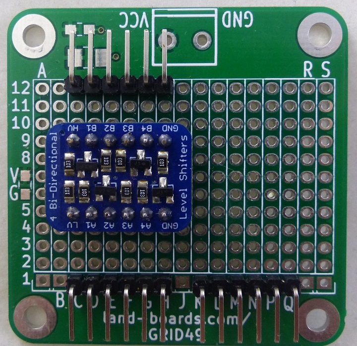
5V Level Shifter (Optional)
- Use for "legacy" 5V Serial target systems
- Not used for 3.3V systems
- Convert 3.3V QT Py Tx/Rx/RTS/CTS to "legacy" 5V
- Isolated 3.3V/5V power
- Common Ground
- Built on GRID49 card
- Adafruit 4-channel I2C-safe Bi-directional Logic Level Converter
- SH-LEV-01 - New
QTPy49-01 Card Cabling
- QTPy49-01 Card has function specific headers
QTPy49-01 Card to MyMenu Cabling
| QTPy49 | SIGNAL | MyMenu | COLOR |
|---|---|---|---|
| J5-1 | GND | P2-1 | BLK |
| J5-2 | +3.3V | P2-2 | RED |
| J5-3 | SDA | P2-3 | WHT |
| J5-4 | SCL | P2-4 | BRN |
QTPy49 Card to Host Serial
| QTPy49 | SIGNAL | COLOR |
|---|---|---|
| J8-3 (D1) | RTS* (in) | GRY |
| J7-1 (D2) | CTS* (out) | ORA |
| J4-4 (RX) | RX | BRN |
| J4-3 (TX) | TX | WHT |
| J4-2 (VCC) | +3.3V | Xlator (only) |
| J4-1 (GND) | GND | BLK |
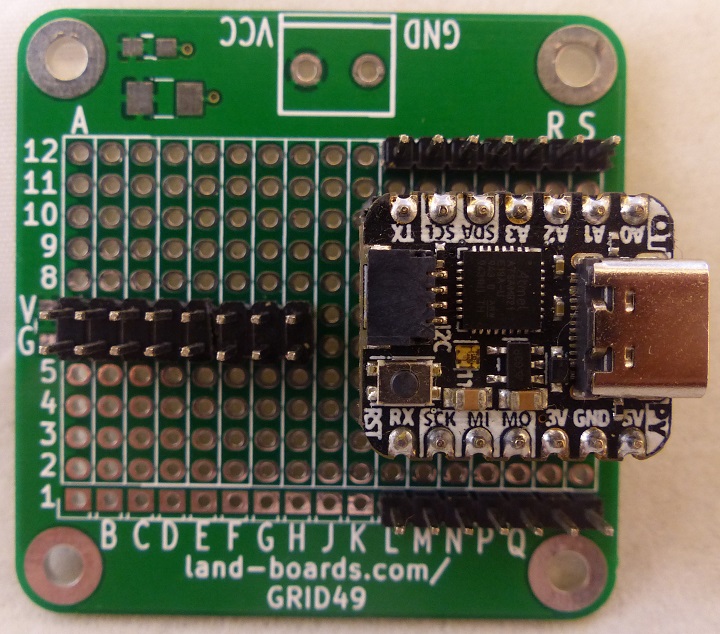
QT Py Breakout Card (Alternate)
- Do not install 5mm Terminal Block
- Power via USB C cable
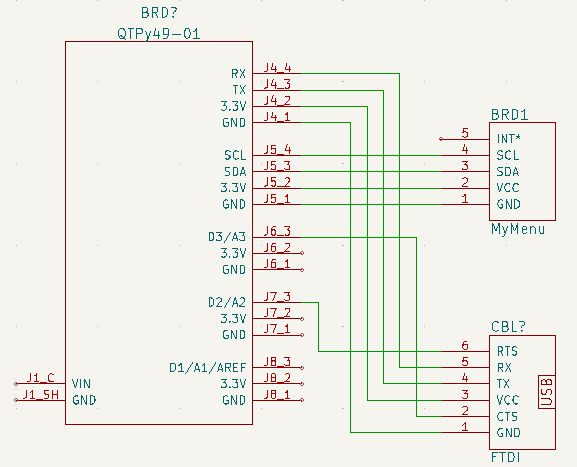
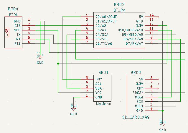
QT Py Breakout Card (on GRID49 card) Cabling
- GRID49 card
- QT Py uses (2) 1x7 male headers for signals
- Cut off 1 set of holes of (2) female housings to make 1x7 female headers
- SD Card uses (1) 1x8 header
- MyMenu uses (1) 1x5 header
- QT Py uses 2x8 header for 3.3V and Ground
- Use 2x3 female housings
- 40mm cables to Host Target
QT Py Breakout Card Cabling
| QT Py | SIGNAL | CARD | PIN | COLOR |
|---|---|---|---|---|
| 01 (AD0) | INT(AD0) | MyMenu | P2-5 | GRY |
| 02 (AD1) | RTS* | TARGET | TBD | GRY |
| 03 (AD2) | CTS* | TARGET | TBD | ORA |
| 04 (AD3) | SS* | SD_CARD | J1-5 | GRY |
| 05 (SDA) | SDA | MyMenu | P2-3 | WHT |
| 06 (SCL) | SCL | MyMenu | P2-4 | BRN |
| 07 (TX) | TX | TARGET | TBD | WHT |
| 08 (RX) | RX | TARGET | TBD | BRN |
| 09 (SCK) | SCK | SD_CARD | J1-3 | BLU |
| 10 (MI) | MISO | SD_CARD | J1-2 | BRN |
| 11 (MO) | MOSI | SD_CARD | J1-4 | WHT |
| 12 (3V) | +3.3V | GRID49 | Q7 | WIRE |
| 13 (GND) | GND | GRID49 | R7 | WIRE |
| 14 (5V) | 5V | N/C | ||
| PWR-01 | +3.3V | SD_CARD | J1-8 | RED |
| PWR-02 | +3.3V | TARGET | TBD | RED |
| PWR-03 | +3.3V | MyMenu | P2-2 | RED |
| PWR-14 | GND | MyMenu | P2-1 | BLK |
| PWR-15 | GND | SD_CARD | J1-1 | BLK |
| PWR-16 | GND | TARGET | TBD | BLK |
Arduino Software
- i2cscan of attached cards shows OLED at 0x3c and MCP23008 at 0x20
I2C addresses found: ['0x20', '0x3c']
Arduino Software Development Environment
- Developed using Arduino IDE V1.8.xx
- Arduino IDE Setup for QT Py
- Requires Arduino IDE version 1.8 or higher
- Add to Preferences Additional Boards Manager URLs
https://adafruit.github.io/arduino-board-index/package_adafruit_index.json
pinMode(pin, INPUT_PULLUP)

#if defined(ARDUINO_SAMD_ZERO) && defined(SERIAL_PORT_USBVIRTUAL)
  // Required for Serial on Zero based boards
  #define Serial SERIAL_PORT_USBVIRTUAL
#endif

const char str[] = "My very long string";
Arduino Human Interface Design (HID)
- Menu driven
- OLED display
Arduino SD Card
- Library
- Example files
Arduino SD Card Library
- SD Card library
- The SD library allows for reading from and writing to SD cards, e.g. on the Arduino Ethernet Shield
- Based on sdfatlib
- The library supports FAT16 and FAT32 file systems on standard SD cards and SDHC cards
- It uses short 8.3 names for files
- The file names passed to the SD library functions can include paths separated by forward-slashes, /, e.g. “directory/filename.txt”
- Because the working directory is always the root of the SD card, a name refers to the same file whether or not it includes a leading slash (e.g. “/file.txt” is equivalent to “file.txt”)
- As of version 1.0, the library supports opening multiple files.
- The communication between the microcontroller and the SD card uses SPI, which takes place on digital pins 11, 12, and 13 (on most Arduino boards) or 50, 51, and 52 (Arduino Mega)
- Additionally, another pin must be used to select the SD card
- This can be the hardware SS pin - pin 10 (on most Arduino boards) or pin 53 (on the Mega) - or another pin specified in the call to SD.begin()
Arduino SD Card Example Code
- SD Card example Code
- Read and Write File example
- Read Card Information
- Read a file from a SD card using the SD library and send it over the serial port
- Create and destroy a file on a SD card
- List the files available in the directory of the SD card
Arduino SD Card Connections
- Uses default board SPI pins
- Uses D3 as chip select
Serial
- Serial Reference
- Serial.begin(speed)
- Serial.available()
- Get the number of bytes (characters) available for reading from the serial port.
- This is data that’s already arrived and stored in the serial receive buffer (which holds 64 bytes).
- Turn off/on receive handshake based on Serial.available() count and storage
- Serial.write()
- Writes binary data to the serial port
- This data is sent as a byte or series of bytes
- To send the characters representing the digits of a number use the print() function instead.
- Syntax
Serial.write(val)
Serial.write(str)
Serial.write(buf, len)
CircuitPython Software
- CircuitPython has several advantages over Arduino IDE
- Build-test-built cycle time much faster
- Much easier to do list processing for directory structure
- Speed not critical in this application
- Not enough SRAM with SAMD version of the card
- RP2040 version of the card has plenty of SRAM
- XAIO RP2040 is $5.40 and ships quickly from US Warehouse
CircuitPython Software Development Environment
- CircuitPython repo
- SDLoader GitHub repo
- Use Thonny IDE
- Left click bottom right corner
- Select CircuitPython (generic)
- Left click bottom right corner
- Select Configure Interpreter
- Select USB Serial Device (COM<x)
- Pins list
import board
dir(board)
['__class__', '__name__', 'A0', 'A1', 'A2', 'A3', 'D0', 'D1', 'D10', 'D2', 'D3', 'D4', 'D5', 'D6', 'D7', 'D8', 'D9', 'I2C', 'LED', 'LED_BLUE', 'LED_GREEN', 'LED_RED', 'MISO', 'MOSI', 'NEOPIXEL', 'NEOPIXEL_POWER', 'RX', 'SCK', 'SCL', 'SDA', 'SPI', 'TX', 'UART', 'board_id']

>>> print(board.board_id)
seeeduino_xiao_rp2040
Install CircuitPython on Seeed XIAO RP2040
- Long press the "BOOT" button. (The "B" is written on the board shown to the right)
- Connect the XIAO PR2040 to your computer while you still pressing the button.
- The computer then will appear a disk driver(RP1-RP2)
- Download the XIAO-RP2040-CircuitPython.uf2 file for XIAO RP2040
- Drag the .uf2 file to the disk driver("RP1-RP2")
- Check the disk drive if the name has changed to "CIRCUITPY" (takes a few seconds)
- Free memory
>>> import gc
>>> gc.mem_free()
208128
>>> import time
>>> gc.mem_free()
207952
CircuitPython Human Interface Design (HID)
- MyMenu card
- 0.91" OLED
- 3 LEDs
- 5 pushbuttons
- i2cscan of attached cards shows OLED at 0x3c and MCP23008 at 0x21
- Added i2cscan code to find the MCP23008 on the MyMenu card
- MyMenu demo/test code
- Read pushbuttons
- Write OLED
- Write LEDs
- Exit by pressing Select button
CircuitPython SD Card
- SD card module reference
- storage module reference
- Using sdcardio
- Listing files on SD card
- sdcardio class constructor
sdcardio.SDCard(bus: busio.SPI, cs: microcontroller.Pin, baudrate: int = 8000000)
Example code
>>> %Run -c $EDITOR_CONTENT
Files on filesystem:
====================
System Volume Information/               Size:       0 by
   WPSettings.dat                        Size:      12 by
   IndexerVolumeGuid                     Size:      76 by
SuperStarTrek.bas                        Size:    20.0 KB
scramble.bas                             Size:    19.2 KB
CivilWar.bas                             Size:    13.5 KB
>>>
- Storing path, file name as set pairs, gives
dirFileNames [('/sd', 'System Volume Information'), ('/sd/System Volume Information', 'WPSettings.dat'), ('/sd/System Volume Information', 'IndexerVolumeGuid'), ('/sd', 'SuperStarTrek.bas'), ('/sd', 'scramble.bas'), ('/sd', 'CivilWar.bas')]
('/sd', 'System Volume Information')
('/sd/System Volume Information', 'WPSettings.dat')
('/sd/System Volume Information', 'IndexerVolumeGuid')
('/sd', 'SuperStarTrek.bas')
('/sd', 'scramble.bas')
('/sd', 'CivilWar.bas')
CircuitPython Serial
- busio UART reference
- Supports RTS/CTS
- Constructor
lassbusio.UART(tx: microcontroller.Pin, rx: microcontroller.Pin, *, baudrate: int = 9600, bits: int = 8, parity: Optional[Parity] = None, stop: int = 1, timeout: float = 1, receiver_buffer_size: int = 64)
- RTS, CTS pins defines on QT Py RP2040
- RTS = pin D2
- CTS = pin D3
`
