Difference between revisions of "SYNTH-MIDI-CTL-01"
Jump to navigation
Jump to search
Blwikiadmin (talk | contribs) |
Blwikiadmin (talk | contribs) (→Videos) |
||
| (3 intermediate revisions by the same user not shown) | |||
| Line 64: | Line 64: | ||
==== Note to CV Mapping ==== | ==== Note to CV Mapping ==== | ||
| + | * [https://www.inspiredacoustics.com/en/MIDI_note_numbers_and_center_frequencies#:~:text=The%20formula%20connecting%20the%20MIDI%20note%20number%20and,440%20%E2%8B%85%202%20%28n%20%E2%88%92%2069%29%20%2F%2012 MIDI Note Mapping] | ||
* There is no standard MIDI note to CV value | * There is no standard MIDI note to CV value | ||
| − | * Differs widely by manufacturer and even model within mfg | + | ** [https://learningmodular.com/matching-octaves-in-your-modular/ Differs widely by manufacturer and even model within mfg] |
* There are bipolar and unipolar implementations | * There are bipolar and unipolar implementations | ||
* This implementation only makes 0-5V output voltages | * This implementation only makes 0-5V output voltages | ||
| Line 109: | Line 110: | ||
<video type="youtube">aPUvFdmg6eM</video> | <video type="youtube">aPUvFdmg6eM</video> | ||
| + | |||
| + | * MIDI Clock explained | ||
| + | |||
| + | <video type="youtube">gDO8Q3GK1eM</video> | ||
== Software == | == Software == | ||
Latest revision as of 13:52, 26 October 2022
Contents
Features
- Adapted from HAGIWO's MIDI to CV module
- Translate from Japanese to English using browser
- XAIO RP2040 CPU
- Arduino MIDI library has not yet been ported to Pico so will need to use CircuitPython MIDI Library
- MIDI In/Out
- Standard MIDI Jacks
- MIDI out jack for future functionality
- (2) 0-5V Analog CV outs
- MCP4822 12-bit D/A - SPI Interface
- Use with SYNTH-VCO-01
- CV1 = V/OCT
- CV2 = MOD
- (2) Digital Outs, eX:
- Gate
- Clock
- Pot supports setting Clock rate
- Standard EuroRack 16 pin header
- Supports 12V in with on-board 5V regulator
- 5V regulator can be not installed if 5V is available on EuroRack connection
- Card is not a Eurorack card
- Probably too deep, needs cabling
- (6) 6-32 Mounting holes
- Stacks with SYNTH-VCO-01 card
RP2040 Pin Assignments
- Pins
- A0, P26 = CLK_POT
- D2 = SPI_SS
- D3 = Gate (Out)
- D4 = MIDI Clk (Out)
- D5 = SPI_LDAC
- D6/TX - MIDI_Out
- D7/RX = MIDI In
- D8 = SPI_SCK
- D9 = Unused
- D10 = MOSI
Connectors
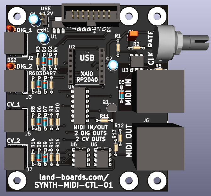
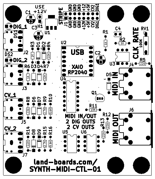
H1 - Use +12V
J1 - Power
- Eurorack compatible pinout
- Fits a shrouded connector with some interference with Voltage Regulator U1
J2, J3 - Digital Outs
J4 - MIDI In
J5, J7 - Control Voltages (CV) Out
- CVs are generated by MCP4822 12-bit D/A
- Output amplifier shifts 0-3.3V from A/D to 0-5V for CV
Note to CV Mapping
- MIDI Note Mapping
- There is no standard MIDI note to CV value
- There are bipolar and unipolar implementations
- This implementation only makes 0-5V output voltages
- Model on Doepfer A-110-1 Standard VCO
C2 = First Note On = 36 velocity 100, Note CV = 0, volts 0.0
C3 = First Note On = 48 velocity 100, Note CV = 819, volts 0.999756
C4 = First Note On = 60 velocity 100, Note CV = 1638, volts 1.99951
C5 = First Note On = 72 velocity 100, Note CV = 2458, volts 3.00049
C6 = First Note On = 84 velocity 100, Note CV = 3277, volts 4.00024
C7 = First Note On = 96 velocity 100, Note CV = 4095, volts 4.99878
CV Scaling
- RP2040 runs at 3.3V
- MCP4822 Dual D/A runs at 3.3V
- Since power supply is 3.3V, can only use the 1X output gain
- Full-scale voltage = 2.048V
- Op Amp drivers out
- Scale output voltage by 5.0/2.048 = 2.4414
- Non-Inverting Op Amp gain = 1 + (Rf/R_to_Gnd)
- Rf/R_to_Gnd = 2.4414-1 = 1.4414
- Rf = 5.6K, R_to_Gnd = 3.9K = 1.436 ratio
- error = 0.3%, resistors are 2%
- Rf = 5.6K, R_to_Gnd = 3.9K = 1.436 ratio
- Can adjust out errors in the Note to CV table
J6 - MIDO Out
- Not used but here for future operation
- Perhaps make USB MIDI to DIN-5 MIDI (In/Out)
Videos
- Similar design
- Arduino NANO and MCP4822 at 5V
- Could only generate 0-4.096 for 4 octaves?
- Due to internal 2.048 voltage reference and 2x gain opamp
- MIDI Clock explained
Software
- MIDI 1.0 Control Change Messages
- HAGIWO 's code runs on an Arduino NANO and was developed in the Arduino IDE
- However, there's no Arduino MIDI library for the RP2040
- This is a port of Arduino code to CircuitPython done in pieces
HAGIWO code baseline
- SYNTHMIDICTL01.ino
- Runs on Arduino NANO
- Used as baseline and converted to CircuitPython
CircuitPython
- synth_midi_ctl_01_001.py
- Toggles the GATE, CLK lines
- synth_midi_ctl_01_002.py
- Blinks the GATE, CLK lines
- MIDI over USB
- Parses MIDI messages, print to REPL
- Pick out single notes since SYNTH is monophonic
- synth_midi_ctl_01_003.py
- Working code
- SYNTH-MIDI-CTL-01_RND_Pitch-Mod.py
- Generates random pitch/mod outputs to LFO
- Speed pot sets note rates from 0.1 secs/note to 1.1 sec/note
- Tested with ER-VCO-03
SPI Code
# imports
import board
import busio
import digitalio

# Set up Chip Select pin
cs = digitalio.DigitalInOut(board.D2)
cs.direction = digitalio.Direction.OUTPUT
cs.value = True

# Create an interface to the SPI hardware bus
spi = busio.SPI(board.SCK, MISO=board.MISO)

# Lock the bus

while not spi.try_lock():
    pass

# The busio.SPI.configure() function is called to configure the speed, phase, and polarity of the SPI bus.
# It’s important to always call configure after locking the bus and before talking to your device as communication
# with other devices might have changed the speed, polarity, etc.
# You’ll need to look up the exact speed and other values from your device’s datasheet.
# For the MAX31855 (example) we’ll use a speed of 5mhz and a polarity and phase of 0 (sometimes called mode 0).

spi.configure(baudrate=5000000, phase=0, polarity=0)
cs.value = False

# Read example (not used)
# result = bytearray(4)
# spi.readinto(result)
# cs.value = True
# result
# bytearray(b'\x01\xa8\x1a\xf0')

# Write example
spi.configure(baudrate=5000000, phase=0, polarity=0)
cs.value = False
spi.write(bytes([0x01, 0xFF]))
cs.value = True

# Need to unlock bus when done
spi.unlock()
Issues
Rev 2
- Moved U4 down a bit
- Add 0.1uF cap MIDI In pin 2 to GND
- Double inverted clocks
- Rev 1 had single inversion
- Will be software difference to invert/not invert clocks
- Moved MIDI In off 74HC14 since it is 5V out on 74HC14
Rev 1 Checkout
- D9 s/b 1N914
- s/s R1 has 1K, P/L has 2.7K
- R1 pullup could be moved to Vcc (+5V)
- DIN-5 J4 could use a 0.1uF cap to logic ground
- J1 fits with a shrouded connector has some interference with Voltage Regulator U1
- U4 is connected to 5V power but drives into XIAO - needs to be clamped to 3.3V
- Cut trace U4-10 (RXD) front side
- Add wire U4-13 to U2-8 (RXD)
- Set CV output to 5V
- Change R9, R15 to 5.6K
- Change R10, R16 to 3.9K

