Difference between revisions of "Si5351 Oscillator Breakout Board"
Jump to navigation
Jump to search
Blwikiadmin (talk | contribs) (Created page with "File:Si5351_001_720px.jpg == Features === File:VFO3.PNG * I2C Daisy-chain connector * 3 outputs * Heat shrinked assembly with cables ==== Measurements ==== * 10 M...") |
Blwikiadmin (talk | contribs) |
||
| (26 intermediate revisions by the same user not shown) | |||
| Line 1: | Line 1: | ||
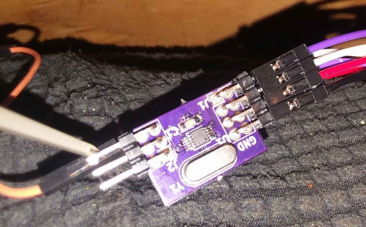
[[File:Si5351_001_720px.jpg]] | [[File:Si5351_001_720px.jpg]] | ||
| − | == Features === | + | == Features == |
| + | |||
| + | * I2C Daisy-chain connector | ||
| + | * 3 outputs | ||
| + | * 25 or 27 MHz crystal (Rev 1) | ||
| + | * 27 MHz TCXO (Rev 3) | ||
| + | * Can be used as a heat shrinked assembly with cables | ||
| + | |||
| + | == Pinout == | ||
[[File:VFO3.PNG]] | [[File:VFO3.PNG]] | ||
| − | + | === J1 - Daisy-chained I2C === | |
| − | * 3 | + | |
| − | * | + | # SCL |
| + | # SDA | ||
| + | # +3.3V | ||
| + | # GND | ||
| + | |||
| + | === J2 - VFO Outputs === | ||
| + | |||
| + | * VFO out / GND Pairs | ||
| + | |||
| + | # VFO0 | ||
| + | # VFO1 | ||
| + | # VFO2 | ||
| + | |||
| + | == Test Setup == | ||
| + | |||
| + | === Test Hardware === | ||
| + | |||
| + | * [[Arduino Pro Mini]] | ||
| + | ** 3.3V/8MHz | ||
| + | * Rotary Encoder/Breakout Board | ||
| + | * 128x32 OLED | ||
| + | * Breadboard Power Supply | ||
| + | ** 3.3V operation | ||
| + | |||
| + | === Test Software === | ||
| + | |||
| + | * [https://github.com/land-boards/lb-Arduino-Code/tree/master/LBCards/I2C-VFO3 I2C-VFO3 Arduino Code on GitHub] | ||
| − | + | == Measurements == | |
* 10 MHz FFT | * 10 MHz FFT | ||
| Line 15: | Line 49: | ||
[[File:10MHz_VFO_FFT-01.png]] | [[File:10MHz_VFO_FFT-01.png]] | ||
| + | |||
| + | == Revision History == | ||
| + | |||
| + | === Rev 3 === | ||
| + | |||
| + | * TXCO | ||
| + | * Fixed solder mask clearance | ||
| + | * Tested | ||
| + | ** Correction factor less than +10 Hz at 10 MHz | ||
| + | *** 1ppm (spec 2.5ppm) | ||
| + | |||
| + | === Rev 2 === | ||
| + | |||
| + | * TXCO instead of crystal | ||
| + | * Insufficient solder mask (too big a clearance) | ||
| + | |||
| + | === Rev 1 === | ||
| + | |||
| + | * Used crystal | ||
| + | |||
| + | == Assembly Sheet - Rev 3 == | ||
| + | |||
| + | [[File:I2C-VFO3-CAD-Rev 2_Front_Back.png]] | ||
| + | |||
| + | {| class="wikitable" | ||
| + | ! Qty | ||
| + | ! Value | ||
| + | ! RefDes | ||
| + | ! | ||
| + | ! Qty | ||
| + | ! Value | ||
| + | ! RefDes | ||
| + | |- | ||
| + | | 2 | ||
| + | | 0.1uF | ||
| + | | C1,C2 | ||
| + | | | ||
| + | | 1 | ||
| + | | Header, Right Angle, 2x3 | ||
| + | | J2 | ||
| + | |- | ||
| + | | 2 | ||
| + | | 2.2K | ||
| + | | R1,R2 | ||
| + | | | ||
| + | | 1 | ||
| + | | Header, Right Angle, 2x4 | ||
| + | | J1 | ||
| + | |- | ||
| + | | 1 | ||
| + | | TCXO, 27 MHz [https://www.mouser.com/ProductDetail/559-FOX924B-27 FOX924B-27] | ||
| + | | U2 | ||
| + | | | ||
| + | | | ||
| + | | | ||
| + | | | ||
| + | |- | ||
| + | | 1 | ||
| + | | [https://www.mouser.com/Semiconductors/Clock-Timer-ICs/Clock-Generators-Support-Products/Si5351-Series/_/N-4k38u?P=1y963j3Z1z0z33o&Keyword=Si5351A&FS=True Si5351A] | ||
| + | | U1 | ||
| + | | | ||
| + | | | ||
| + | | | ||
| + | | | ||
| + | |- | ||
| + | |} | ||
Latest revision as of 13:04, 1 November 2021
Contents
Features
- I2C Daisy-chain connector
- 3 outputs
- 25 or 27 MHz crystal (Rev 1)
- 27 MHz TCXO (Rev 3)
- Can be used as a heat shrinked assembly with cables
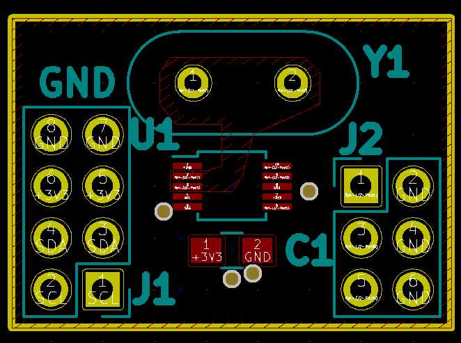
Pinout
J1 - Daisy-chained I2C
- SCL
- SDA
- +3.3V
- GND
J2 - VFO Outputs
- VFO out / GND Pairs
- VFO0
- VFO1
- VFO2
Test Setup
Test Hardware
- Arduino Pro Mini
- 3.3V/8MHz
- Rotary Encoder/Breakout Board
- 128x32 OLED
- Breadboard Power Supply
- 3.3V operation
Test Software
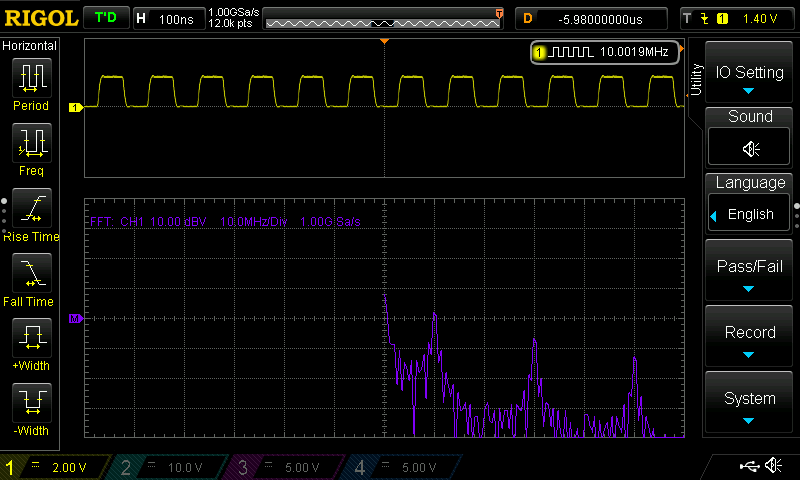
Measurements
- 10 MHz FFT
- Square wave has high odd harmonic content
Revision History
Rev 3
- TXCO
- Fixed solder mask clearance
- Tested
- Correction factor less than +10 Hz at 10 MHz
- 1ppm (spec 2.5ppm)
- Correction factor less than +10 Hz at 10 MHz
Rev 2
- TXCO instead of crystal
- Insufficient solder mask (too big a clearance)
Rev 1
- Used crystal
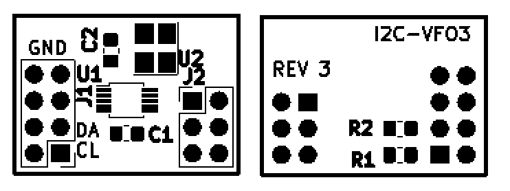
Assembly Sheet - Rev 3
| Qty | Value | RefDes | Qty | Value | RefDes | |
|---|---|---|---|---|---|---|
| 2 | 0.1uF | C1,C2 | 1 | Header, Right Angle, 2x3 | J2 | |
| 2 | 2.2K | R1,R2 | 1 | Header, Right Angle, 2x4 | J1 | |
| 1 | TCXO, 27 MHz FOX924B-27 | U2 | ||||
| 1 | Si5351A | U1 |


