Difference between revisions of "Through-hole Braids"
Jump to navigation
Jump to search
Blwikiadmin (talk | contribs) (→Build) |
Blwikiadmin (talk | contribs) (→Build) |
||
| Line 58: | Line 58: | ||
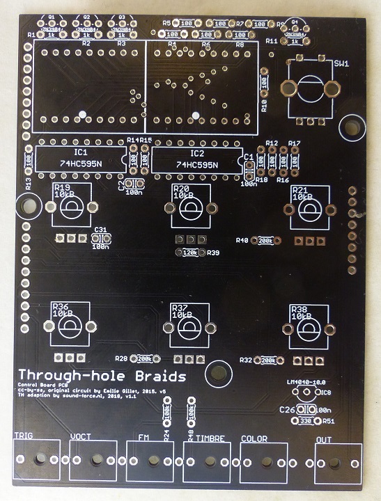
[[file:MI_Braids_P1080733-720.jpg]] | [[file:MI_Braids_P1080733-720.jpg]] | ||
| + | |||
| + | == Parts List == | ||
| + | |||
| + | {| class="wikitable" | ||
| + | ! Qty | ||
| + | ! Index | ||
| + | ! Desc | ||
| + | |- | ||
| + | | 0 | ||
| + | | controls | ||
| + | | | ||
| + | |- | ||
| + | | 14 | ||
| + | | R4-R10, R12-R18 | ||
| + | | 100 Resistor, 1% | ||
| + | |- | ||
| + | | 1 | ||
| + | | R51 | ||
| + | | 330 Resistor, 1% | ||
| + | |- | ||
| + | | 7 | ||
| + | | R1-R3, R11, R22, R23, R55 | ||
| + | | 1k Resistor, 1% | ||
| + | |- | ||
| + | | 1 | ||
| + | | R27 | ||
| + | | 10k Resistor, 1% | ||
| + | |- | ||
| + | | 1 | ||
| + | | R50 | ||
| + | | 20k Resistor, 1% | ||
| + | |- | ||
| + | | 10 | ||
| + | | R30, R31, R34, R35, R41-R44, R52, R53 | ||
| + | | 24.9k Resistor, 1% | ||
| + | |- | ||
| + | | 2 | ||
| + | | R45, R46 | ||
| + | | 39k Resistor, 1% | ||
| + | |- | ||
| + | | 2 | ||
| + | | R25, R26 | ||
| + | | 49.9k Resistor, 1% | ||
| + | |- | ||
| + | | 6 | ||
| + | | R24, R29, R47, R48, R54, R56 | ||
| + | | 100k Resistor, 1% | ||
| + | |- | ||
| + | | 1 | ||
| + | | R39 | ||
| + | | 120k Resistor, 1% | ||
| + | |- | ||
| + | | 3 | ||
| + | | R28, R32, R40 | ||
| + | | 200k Resistor, 1% | ||
| + | |- | ||
| + | | 3 | ||
| + | | R33, R49, R57 (Optional see note, only on Brain 1.2) | ||
| + | | 47 Resistor, 1% | ||
| + | |- | ||
| + | | 1 | ||
| + | | C29 | ||
| + | | 47p Capacitor, ceramic | ||
| + | |- | ||
| + | | 2 | ||
| + | | C21, C22 | ||
| + | | 100p Capacitor, ceramic | ||
| + | |- | ||
| + | | 4 | ||
| + | | C13, C14, C16, C17 | ||
| + | | 1n Capacitor, ceramic | ||
| + | |- | ||
| + | | 13 | ||
| + | | C1-C6, C18, C20, C23, C26, C27, C28, C31 | ||
| + | | 100n Capacitor, ceramic | ||
| + | |- | ||
| + | | 1 | ||
| + | | C8 | ||
| + | | 470n Capacitor, ceramic | ||
| + | |- | ||
| + | | | ||
| + | | Capacitors eletrolytic | ||
| + | | | ||
| + | |- | ||
| + | | 1 | ||
| + | | C24 | ||
| + | | 10u Capacitor, electrolytic NP | ||
| + | |- | ||
| + | | 4 | ||
| + | | C7, C9, C15, C33 | ||
| + | | 10u Capacitor, electrolytic | ||
| + | |- | ||
| + | | 2 | ||
| + | | C25, C30 | ||
| + | | 47u Capacitor, electrolytic | ||
| + | |- | ||
| + | | | ||
| + | | Diodes | ||
| + | | | ||
| + | |- | ||
| + | | 2 | ||
| + | | D1, D2 | ||
| + | | 1N5817 | ||
| + | |- | ||
| + | | | ||
| + | | ICs | ||
| + | | | ||
| + | |- | ||
| + | | 2 | ||
| + | | IC1, IC2 | ||
| + | | SN74HC595 | ||
| + | |- | ||
| + | | 1 | ||
| + | | IC3 | ||
| + | | 2.5V LM4040 Shunt Vref | ||
| + | |- | ||
| + | | 1 | ||
| + | | IC4 | ||
| + | | MCP3204 quad 12-bit ADC | ||
| + | |- | ||
| + | | 1 | ||
| + | | IC5 | ||
| + | | MCP4822 dual 12-bit DAC | ||
| + | |- | ||
| + | | 2 | ||
| + | | IC6, IC11 | ||
| + | | 3.3V LD1117V33 | ||
| + | |- | ||
| + | | 1 | ||
| + | | IC7 | ||
| + | | MCP6004 dual op-amp R2R IO | ||
| + | |- | ||
| + | | 1 | ||
| + | | IC8 | ||
| + | | 10V LM4040 Shunt Vref | ||
| + | |- | ||
| + | | 1 | ||
| + | | IC9 | ||
| + | | TL074 quad op-amp | ||
| + | |- | ||
| + | | 1 | ||
| + | | IC10 | ||
| + | | TL072 dual op-amp | ||
| + | |- | ||
| + | | 6 | ||
| + | | Q1-Q4, Q6, Q7 | ||
| + | | NPN transistor 2N3904 | ||
| + | |- | ||
| + | | 1 | ||
| + | | UC1 | ||
| + | | STM32F103C8T6 NEEDS TO BE 124kb | ||
| + | |- | ||
| + | | 0 | ||
| + | | top | ||
| + | | | ||
| + | |- | ||
| + | | 2 | ||
| + | | DISP1, DISP2 | ||
| + | | 14 segments 2 characters LED module | ||
| + | |- | ||
| + | | 6 | ||
| + | | COLOR, FM, OUT, TIMBRE, TRIG, VOCT | ||
| + | | Vertical jack connector | ||
| + | |- | ||
| + | | 6 | ||
| + | | R19-R21, R36-R38 | ||
| + | | 10k linear pot, 15mm shaft | ||
| + | |- | ||
| + | | 1 | ||
| + | | SW1 | ||
| + | | Encoder, 24 steps w/ clicks, w/ switch | ||
| + | |- | ||
| + | | | ||
| + | | Headers | ||
| + | | | ||
| + | |- | ||
| + | | | ||
| + | | Single row male | ||
| + | | 1X06, 1X10, 1X8, 1X09 | ||
| + | |- | ||
| + | | | ||
| + | | Single row female | ||
| + | | 1X10, 1X8, 1X09, | ||
| + | |- | ||
| + | | 2 | ||
| + | | Female header for the blue pill (optional) | ||
| + | | 1x20 | ||
| + | |- | ||
| + | | | ||
| + | | Euro power | ||
| + | | 2x05 (Preferably shrouded) | ||
| + | |- | ||
| + | | | ||
| + | | Programmer | ||
| + | | | ||
| + | |- | ||
| + | | | ||
| + | | Programmer to program the STM32 board | ||
| + | | | ||
| + | |- | ||
| + | | | ||
| + | | Alternative Serial "programmer" | ||
| + | | FTDI's or CH430 could also work but I have found the CP2102 to be most compatible on Mac. | ||
| + | |- | ||
| + | |} | ||
== Videos == | == Videos == | ||
Revision as of 02:13, 14 November 2022
Contents
Features
- Ordered card set from Sourcery Studios on Tindie
- Vagrant environment for Mutable Instruments modules hacking
- Schematic
- BOM
- Assembly Notes
Show Screen Caps
Braids Show Notes
- Get the PCB set with panel and both PCBs for 9$ at Kristian's Tindie store
- Tindie store
- (Or) Download the Gerber files
- 5pcs Red Common Cathode 7 segment display - MAKE SURE TO CHOOSE COMMON CATHODE
- Get a STM32 Programmer here
- STM32F013CBT8 (128kb version) on ebay... not that many to choose from :/
- The STM32F103C8T6 is the 64kb version and thus too small but SOMETIMES they are 128kb
- Front panel gerber by MyModularJourney
- Braids illustrated. all the waveforms explained
- Emilie Gilet / Mutable Instruments modules Github
- Modular in a Week playlist
- Support Kristian's work on Patreon
- Kristian's Discord server - where you find the mi-th-braids channel and much more]
- See mi-th-braids channel
- See pinned messages
- Braids Manual
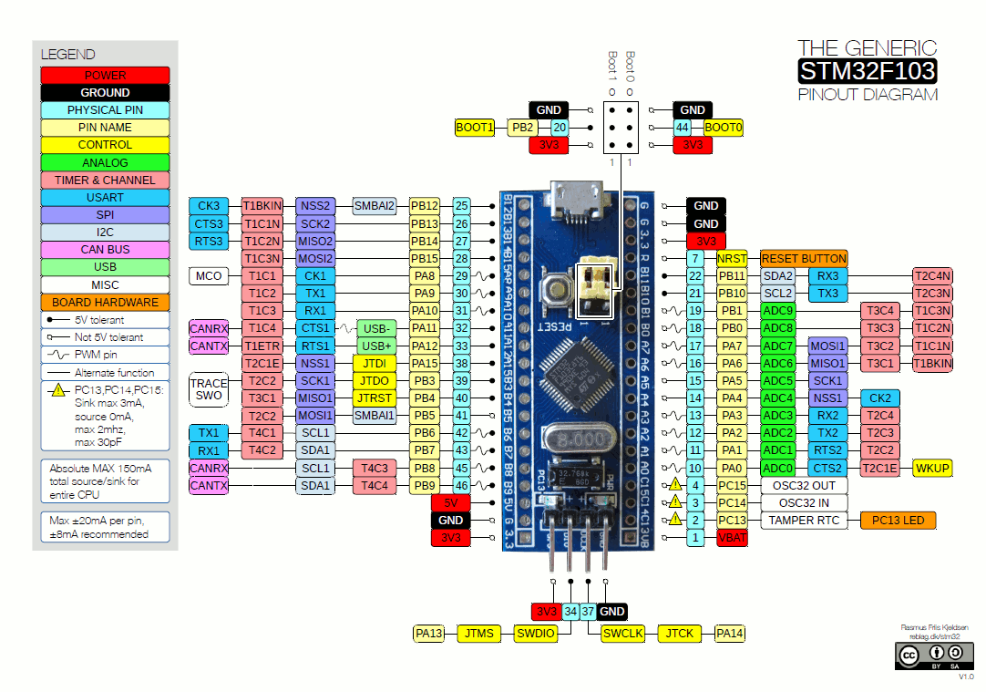
Blue Pill
Build
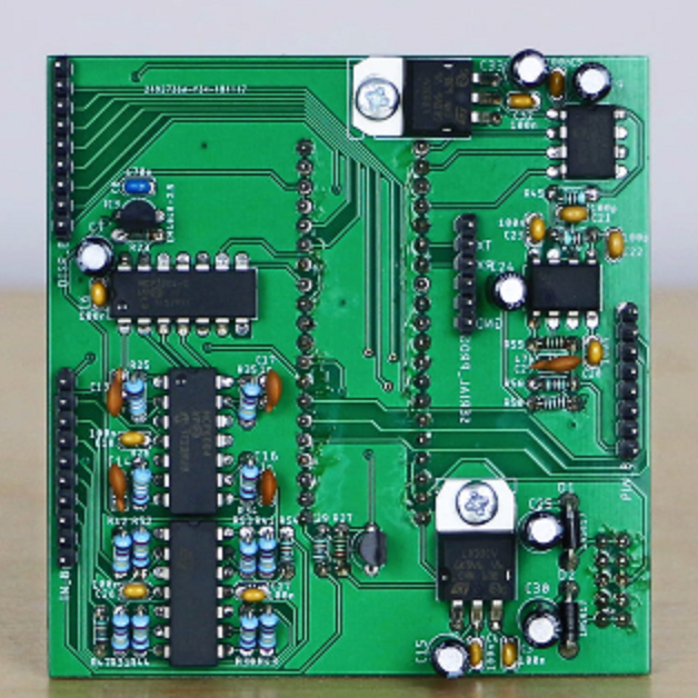
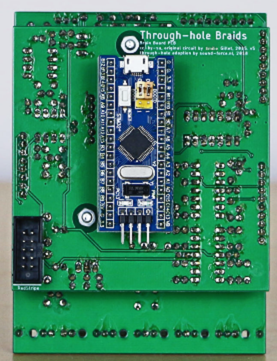
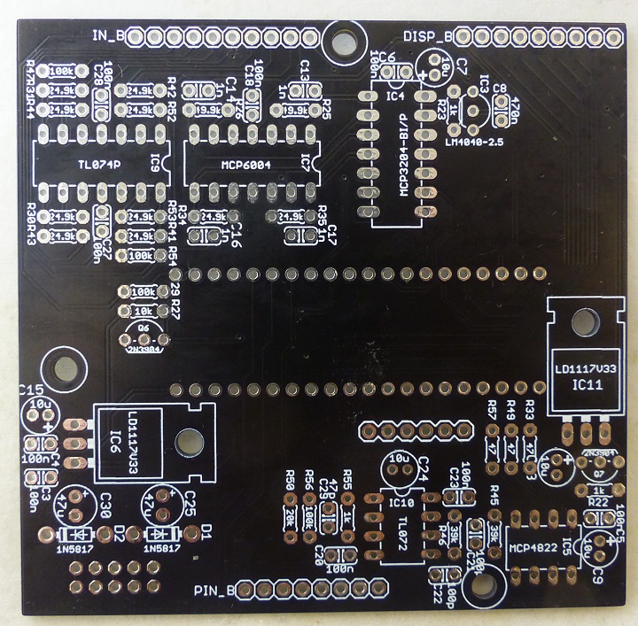
Processing Card
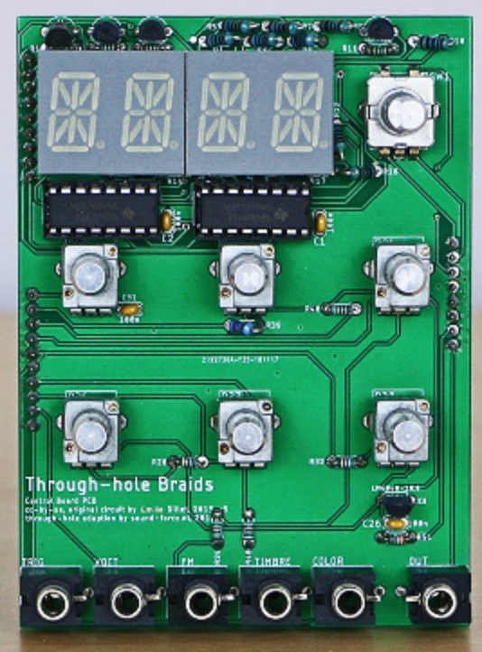
Controls Card
Parts List
| Qty | Index | Desc |
|---|---|---|
| 0 | controls | |
| 14 | R4-R10, R12-R18 | 100 Resistor, 1% |
| 1 | R51 | 330 Resistor, 1% |
| 7 | R1-R3, R11, R22, R23, R55 | 1k Resistor, 1% |
| 1 | R27 | 10k Resistor, 1% |
| 1 | R50 | 20k Resistor, 1% |
| 10 | R30, R31, R34, R35, R41-R44, R52, R53 | 24.9k Resistor, 1% |
| 2 | R45, R46 | 39k Resistor, 1% |
| 2 | R25, R26 | 49.9k Resistor, 1% |
| 6 | R24, R29, R47, R48, R54, R56 | 100k Resistor, 1% |
| 1 | R39 | 120k Resistor, 1% |
| 3 | R28, R32, R40 | 200k Resistor, 1% |
| 3 | R33, R49, R57 (Optional see note, only on Brain 1.2) | 47 Resistor, 1% |
| 1 | C29 | 47p Capacitor, ceramic |
| 2 | C21, C22 | 100p Capacitor, ceramic |
| 4 | C13, C14, C16, C17 | 1n Capacitor, ceramic |
| 13 | C1-C6, C18, C20, C23, C26, C27, C28, C31 | 100n Capacitor, ceramic |
| 1 | C8 | 470n Capacitor, ceramic |
| Capacitors eletrolytic | ||
| 1 | C24 | 10u Capacitor, electrolytic NP |
| 4 | C7, C9, C15, C33 | 10u Capacitor, electrolytic |
| 2 | C25, C30 | 47u Capacitor, electrolytic |
| Diodes | ||
| 2 | D1, D2 | 1N5817 |
| ICs | ||
| 2 | IC1, IC2 | SN74HC595 |
| 1 | IC3 | 2.5V LM4040 Shunt Vref |
| 1 | IC4 | MCP3204 quad 12-bit ADC |
| 1 | IC5 | MCP4822 dual 12-bit DAC |
| 2 | IC6, IC11 | 3.3V LD1117V33 |
| 1 | IC7 | MCP6004 dual op-amp R2R IO |
| 1 | IC8 | 10V LM4040 Shunt Vref |
| 1 | IC9 | TL074 quad op-amp |
| 1 | IC10 | TL072 dual op-amp |
| 6 | Q1-Q4, Q6, Q7 | NPN transistor 2N3904 |
| 1 | UC1 | STM32F103C8T6 NEEDS TO BE 124kb |
| 0 | top | |
| 2 | DISP1, DISP2 | 14 segments 2 characters LED module |
| 6 | COLOR, FM, OUT, TIMBRE, TRIG, VOCT | Vertical jack connector |
| 6 | R19-R21, R36-R38 | 10k linear pot, 15mm shaft |
| 1 | SW1 | Encoder, 24 steps w/ clicks, w/ switch |
| Headers | ||
| Single row male | 1X06, 1X10, 1X8, 1X09 | |
| Single row female | 1X10, 1X8, 1X09, | |
| 2 | Female header for the blue pill (optional) | 1x20 |
| Euro power | 2x05 (Preferably shrouded) | |
| Programmer | ||
| Programmer to program the STM32 board | ||
| Alternative Serial "programmer" | FTDI's or CH430 could also work but I have found the CP2102 to be most compatible on Mac. |
Videos
