Difference between revisions of "TinyPS2"
Jump to navigation
Jump to search
Blwikiadmin (talk | contribs) |
Blwikiadmin (talk | contribs) |
||
| (13 intermediate revisions by the same user not shown) | |||
| Line 29: | Line 29: | ||
[[file:TinyPS2_CPU_Rev4_Conns.PNG]] | [[file:TinyPS2_CPU_Rev4_Conns.PNG]] | ||
| + | |||
| + | <pre> | ||
| + | #define DATAPIN 27 | ||
| + | #define IRQPIN 26 | ||
| + | </pre> | ||
== Connectors == | == Connectors == | ||
| Line 34: | Line 39: | ||
=== J1 - TTL Serial Connector === | === J1 - TTL Serial Connector === | ||
| − | [[file: | + | [[file:TinyPS2_J1_Rev4_Conns.PNG]] |
# VCC (pin nearest to J1 silkscreem) | # VCC (pin nearest to J1 silkscreem) | ||
| Line 45: | Line 50: | ||
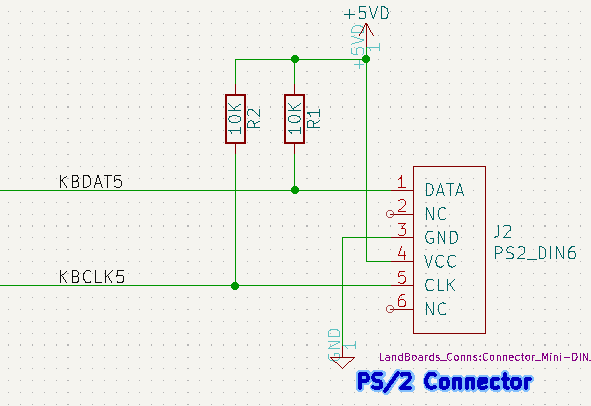
* Standard PS/2 Mini-DIN-6 connector | * Standard PS/2 Mini-DIN-6 connector | ||
| − | [[file: | + | [[file:TinyPS2_J2_Rev4_Conns.PNG]] |
| − | == | + | == Firmware Build Card Rev 4 == |
| − | [[file: | + | [[file:asciifull.png]] |
| − | |||
| − | |||
| − | |||
| − | |||
| − | |||
| − | |||
| − | |||
| − | |||
| − | |||
| − | |||
| − | |||
| − | |||
| − | == | + | === Arduino === |
* Card rev 4 uses a QTPy or XAIO RP2040 CPU | * Card rev 4 uses a QTPy or XAIO RP2040 CPU | ||
* Arduino Library | * Arduino Library | ||
** [https://github.com/techpaul/PS2KeyAdvanced PS2KeyAdvanced] | ** [https://github.com/techpaul/PS2KeyAdvanced PS2KeyAdvanced] | ||
| − | * Example code | + | * [https://github.com/land-boards/lb-Arduino-Code/blob/master/LBCards/TinyPS2/TinyPS2_PCB_Rev4_AdvKbd/TinyPS2_PCB_Rev4_AdvKbd.ino TinyPS2_PCB_Rev4_AdvKbd] - code |
| + | <pre> | ||
| + | #define DATAPIN 27 | ||
| + | #define IRQPIN 26 | ||
| + | </pre> | ||
| + | |||
| + | * Example code produces warning | ||
<pre> | <pre> | ||
| Line 75: | Line 74: | ||
Global variables use 43096 bytes (15%) of dynamic memory, leaving 227240 bytes for local variables. Maximum is 270336 bytes. | Global variables use 43096 bytes (15%) of dynamic memory, leaving 227240 bytes for local variables. Maximum is 270336 bytes. | ||
</pre> | </pre> | ||
| + | |||
| + | * Code works well! | ||
| + | |||
| + | === C++ === | ||
| + | |||
| + | * [https://github.com/tvlad1234/pico-ps2Driv pico-ps2Driv] - SDK C code | ||
| + | |||
| + | === CircuitPython === | ||
* CircuitPython support issues | * CircuitPython support issues | ||
| Line 85: | Line 92: | ||
ImportError: no module named 'ps2io' | ImportError: no module named 'ps2io' | ||
</pre> | </pre> | ||
| − | |||
| − | |||
| − | |||
| − | |||
| − | |||
| − | |||
| − | |||
| − | |||
| − | |||
| − | |||
| − | |||
| − | |||
| − | |||
| − | |||
| − | |||
| − | |||
| − | |||
| − | |||
| − | |||
| − | |||
| − | |||
| − | |||
| − | |||
| − | |||
| − | |||
| − | |||
| − | |||
| − | |||
| − | |||
| − | |||
| − | |||
| − | |||
| − | |||
| − | |||
| − | |||
| − | |||
| − | |||
| − | |||
| − | |||
| − | |||
| − | |||
| − | |||
| − | |||
| − | |||
| − | |||
| − | |||
| − | |||
| − | |||
| − | |||
| − | |||
| − | |||
| − | |||
| − | |||
| − | |||
| − | |||
| − | |||
| − | |||
| − | |||
| − | |||
| − | |||
| − | |||
| − | |||
| − | |||
| − | |||
| − | |||
| − | |||
| − | |||
| − | |||
| − | |||
| − | |||
| − | |||
| − | |||
| − | |||
| − | |||
| − | |||
| − | |||
| − | |||
| − | |||
| − | |||
| − | |||
== Schematic == | == Schematic == | ||
| Line 171: | Line 98: | ||
== Issues == | == Issues == | ||
| + | |||
| + | * [[TinyPS2_Revs_1-3|Revs 1-3 are documented here]] | ||
=== Rev 4 === | === Rev 4 === | ||
| Line 182: | Line 111: | ||
* CPU runs at 3.3VV | * CPU runs at 3.3VV | ||
* 3.3V to 5V level shifter | * 3.3V to 5V level shifter | ||
| − | |||
| − | |||
| − | |||
| − | |||
| − | |||
| − | |||
| − | |||
| − | |||
| − | |||
| − | |||
| − | |||
| − | |||
| − | |||
| − | |||
| − | |||
| − | |||
| − | |||
| − | |||
| − | |||
| − | |||
| − | |||
| − | |||
== Assembly Sheet == | == Assembly Sheet == | ||
| − | * [[TinyPS2 Rev | + | * [[TinyPS2 Rev 4 Assembly Sheet]] |
| − | |||
Latest revision as of 16:51, 15 August 2022
See TinyPS2 Revs 1-3 for ATTiny85 based build
Contents
Introduction
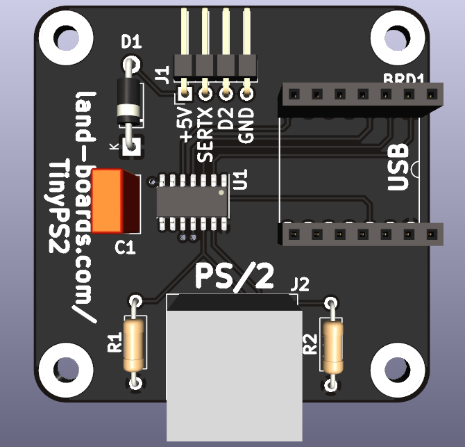
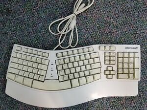
It is getting difficult to find ASCII serial keyboards for use in Retro-Computer projects. This card fills that need. The card is a PS/2 keyboard to TTL Level Serial adapter. PS/2 keyboards are still widely available.
Features
- QT Py (RP2040 based)
- Run at 125 MHz
- 2MB of In System Programmable (ISP) flash
- 264KB of SRAM
- 115,200 baud serial
- 57,600-250,000 are build time options
- 49x49mm ODAS form factor
- (4) 4-40 mounting holes
- 3.3V or 5V operation
- Current measurement
- TBD @ 5V (without keyboard)
- TBD @ 5V (including keyboard)
- TBD @ 3.3V (including keyboard)
- Does not require a keyboard that works at 3.3V
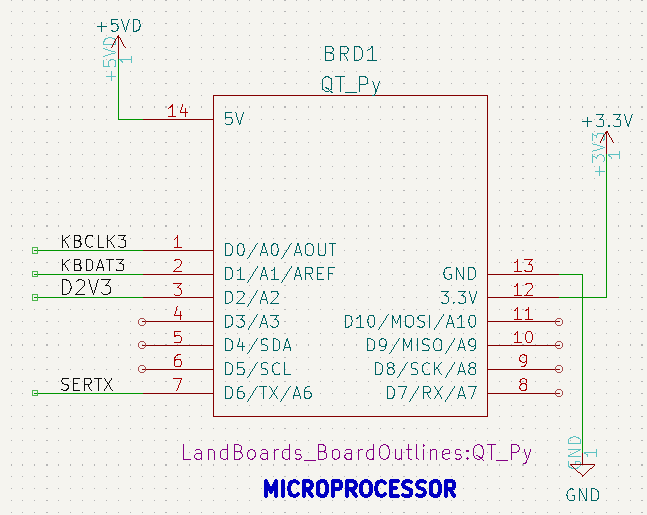
CPU Connections
#define DATAPIN 27
#define IRQPIN  26
Connectors
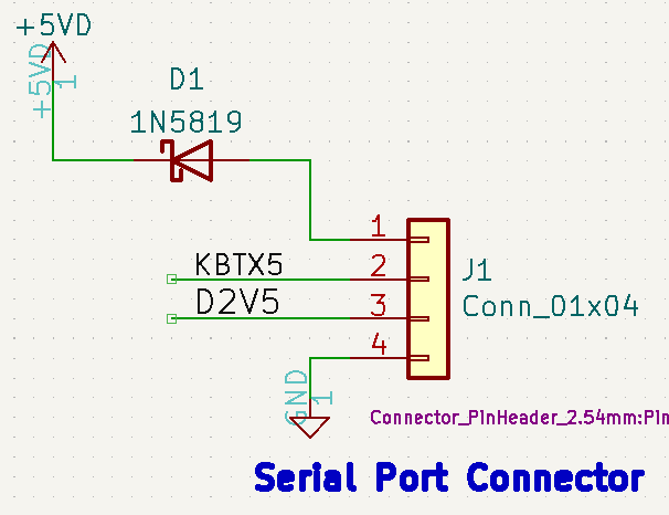
J1 - TTL Serial Connector
- VCC (pin nearest to J1 silkscreem)
- SERTX
- N/C
- GND
J2 - PS/2
- Standard PS/2 Mini-DIN-6 connector
Firmware Build Card Rev 4
Arduino
- Card rev 4 uses a QTPy or XAIO RP2040 CPU
- Arduino Library
- TinyPS2_PCB_Rev4_AdvKbd - code
#define DATAPIN 27
#define IRQPIN  26
- Example code produces warning
WARNING: library PS2KeyAdvanced claims to run on avr, sam, samd1, stm32, esp32 architecture(s) and may be incompatible with your current board which runs on rp2040 architecture(s).
Sketch uses 82336 bytes (0%) of program storage space. Maximum is 16777216 bytes.
Global variables use 43096 bytes (15%) of dynamic memory, leaving 227240 bytes for local variables. Maximum is 270336 bytes.
- Code works well!
C++
- pico-ps2Driv - SDK C code
CircuitPython
- CircuitPython support issues
- PS/2 Library - Not in Pico core modules
>>> import ps2io
Traceback (most recent call last):
  File "<stdin>", line 1, in <module>
ImportError: no module named 'ps2io'
Schematic
Issues
Rev 4
- Changed CPU
- Was 8 MHz ATTiny85
- Changed to QT PY or XAIO
- Changed pin usage
- Uses Hardware Transmitter in CPU
- Keyboard runs at 5V
- CPU runs at 3.3VV
- 3.3V to 5V level shifter
