Difference between revisions of "VFO-003"
Jump to navigation
Jump to search
Blwikiadmin (talk | contribs) |
Blwikiadmin (talk | contribs) |
||
| Line 35: | Line 35: | ||
[[VFO-003 Assembly Sheet - Rev 1]] | [[VFO-003 Assembly Sheet - Rev 1]] | ||
| + | |||
| + | == Connectors === | ||
| + | |||
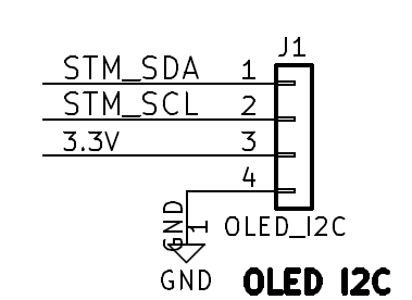
| + | [[file:VFO-003_J1.PNG]] | ||
| + | |||
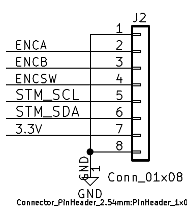
| + | [[file:VFO-003_J2.PNG]] | ||
| + | |||
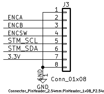
| + | [[file:VFO-003_J3.PNG]] | ||
| + | |||
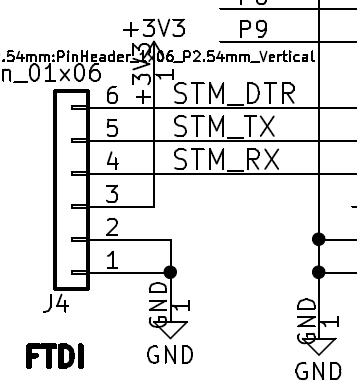
| + | [[file:VFO-003_J4.PNG]] | ||
| + | |||
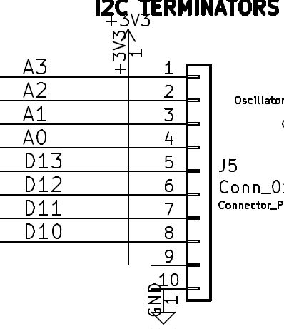
| + | [[file:VFO-003_J5.PNG]] | ||
| + | |||
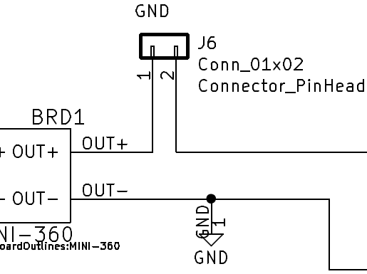
| + | [[file:VFO-003_J6.PNG]] | ||
| + | |||
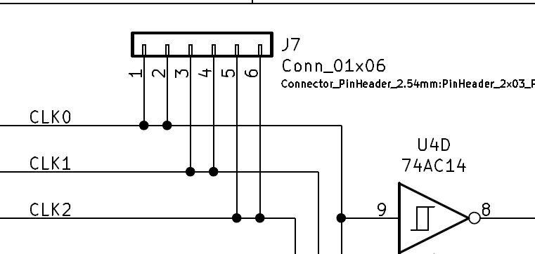
| + | [[file:VFO-003_J7.PNG]] | ||
| + | |||
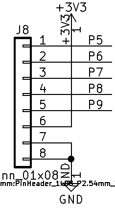
| + | [[file:VFO-003_J8.PNG]] | ||
Revision as of 11:48, 29 July 2021
Features
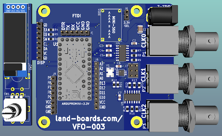
- Software controlled VFO
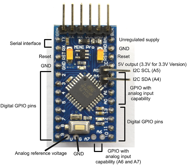
- Arduino Pro Mini Microprocessor
- 8-bit ATMEGA328 CPU
- 8 MHz
- 3.3V I/O
- Detachable Rotary Encoder/OLED card
- SSD1306 OLED Display
- I2C Interface
- Controls frequencies with rotary encoder
- 100 Hz, 1 KHz, 10 KHz, 100 KHz, 1 MHz, 10 MHz steps (software controllable
- SSD1306 OLED Display
- Si5351A Oscillator
- 3 Outputs
- 25 or 27 MHz crystal
- I2C Interface
- Power
- MINI-360 DC/DC Buck regulator
- 7-24 VDC
- Fits in standard extruded enclosures
Arduino Pro Mini
Schematic
Assembly Sheet / Parts List
VFO-003 Assembly Sheet - Rev 1
