Difference between revisions of "VFO-003 Assembly Sheet - Rev 1"
Jump to navigation
Jump to search
Blwikiadmin (talk | contribs) (→Notes) |
Blwikiadmin (talk | contribs) (→PL) |
||
| Line 17: | Line 17: | ||
| | | | ||
| 3 | | 3 | ||
| − | | SMA-F ( | + | | SMA-F (NOTE 3) |
| J9-J11 | | J9-J11 | ||
|- | |- | ||
| Line 25: | Line 25: | ||
| | | | ||
| 3 | | 3 | ||
| − | | BNC ( | + | | [https://www.mouser.com/ProductDetail/523-31-5431-10RFX BNC] (NOTE 3) |
| P1-P3 | | P1-P3 | ||
|- | |- | ||
Revision as of 20:48, 13 October 2021
PL
| Qty | Value | RefDes | Qty | Value | RefDes | |
|---|---|---|---|---|---|---|
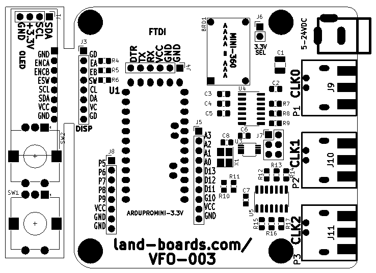
| 7 | 0.1uF | C2-C8 (0805) | 3 | SMA-F (NOTE 3) | J9-J11 | |
| 1 | 10uF | C1 (1206) | 3 | BNC (NOTE 3) | P1-P3 | |
| 9 | 150 | R7-R9,R12-R17 | 1 | Conn, Strt, 1x2 | J6 | |
| 3 | 1K | R4-R6 | 1 | Conn, Strt, 1x6 | J4 | |
| 5 | 2.2K | R1-R3,R10,R11 | 3 | Conn, 1x8 | J2,J3,J8 | |
| 2 | 74AC14 | U4,U5 | 1 | Conn, 1x10 | J5 | |
| 1 | Si5351A | U3 | 1 | Conn, 2x3 | J7 | |
| 1 | ASE-xxxMHz | X1 | 1 | DCJ0202 | J99 | |
| 1 | MINI-360 (Note 1) | BRD1 | 2 | Rotary_Encoder_Switch | SW1 OR SW2 | |
| 1 | ARDUPROMINI-3.3V (Note 2) | U1 | 1 | OLED_I2C | J1 |
Notes
- Mini360 gets installed with the inductor towards the edge of the card (output side)
- 3.3V version of the Arduino Pro Mini. Requires 3 pin header for A4, A5 (I2C)
