Difference between revisions of "ArduinoInABox"
Jump to navigation
Jump to search
Blwikiadmin (talk | contribs) |
Blwikiadmin (talk | contribs) |
||
| Line 94: | Line 94: | ||
=== J6 - Voltage Adjustment === | === J6 - Voltage Adjustment === | ||
| − | * Adjust voltage for 3.3V or 5V | + | * Adjust voltage for 3.3V or 5V to match Pro Mini voltage before installing jumper |
=== J9 - Use Raw Power === | === J9 - Use Raw Power === | ||
Revision as of 20:07, 21 May 2022
Contents
Features
- Arduino Pro Mini
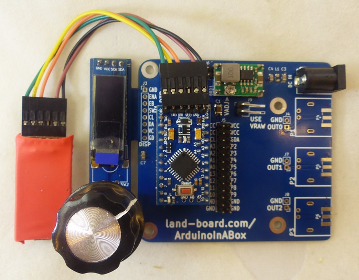
- Detachable Human Interface design (HID)
- Flexible Input power
- On-board DC/DC buck regulator allows 7-23V input
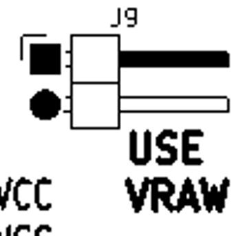
- Direct 7-9V input (USE VRAW jumper)
- 3.3V of 5V Arduino support
- Measured 12 mA with 9V input and 3.3V Arduino Pro Mini
- I/O Boards
- DB-25
- Mounts in a standard extruded Aluminum enclosure
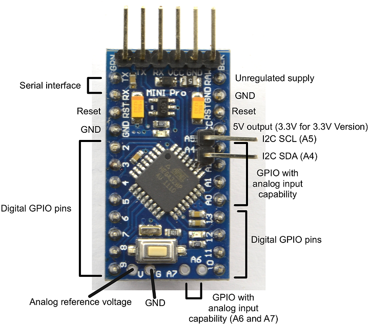
Arduino Pro Mini
- Inexpensive and widely available
- Arduino Pro Mini sCHEMATIC
- I/O - 14 digital input/output pins (of which 6 can be used as PWM outputs)
- Serial: 0 (RX) and 1 (TX).
- Used to receive (RX) and transmit (TX) TTL serial data.
- These pins are connected to the TX-0 and RX-1 pins of the six pin header.
- External Interrupts: 2 and 3.
- These pins can be configured to trigger an interrupt on a low value, a rising or falling edge, or a change in value.
- See the attachInterrupt function for details.
- PWM: 3, 5, 6, 9, 10, and 11.
- Provide 8-bit PWM output with the analogWrite function.
- SPI: 10 (SS), 11 (MOSI), 12 (MISO), 13 (SCK).
- These pins support SPI communication, which, although provided by the underlying hardware.
- LED: 13.
- There is a built-in LED connected to digital pin 13.
- When the pin is HIGH value, the LED is on, when the pin is LOW, it's off.
- 6 analog inputs
- Serial: 0 (RX) and 1 (TX).
- On-board resonator (8 or 16 MHz)
- Reset button
- A six pin header can be connected to an FTDI cable provide USB power and communication to the board
- 3.3 or 5V
- 8 MHz (3.3V) or 16 MHz (5V)
- Programmable in Arduino IDE
Detachable Human Interface design (HID)
- OLED
- 128x32 or 128x64
- u8x8 driver - 6.2KB overhead
- Rotary Encoder with switch
- Can leave attached to main board until installing in box
Input power
- Wide input voltage range
- 5-23V (for 3.3V Arduino Pro Mini)
- 7-23V (for 5V Arduino Pro Mini)
- 2.1mm DC Power Connector Jack
- RF filter into Switching regulator board
- 2nd RF filter into HID card
- Mini360 Switching Mode Power Supply
- About $1
- Jumper to use raw input and not populate the Mini360
- Uses the inputs jack as RAW power into the Arduino Pro Mini
- 3.35-12 V (3.3V model) or 5-12 V (5V model)
Connectors
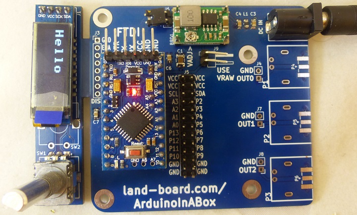
J1 - OLED
- Pinout
- SDA
- SCL
- +VCC
- GND
J2 - HID (on HID card)
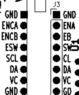
J3 - On base board
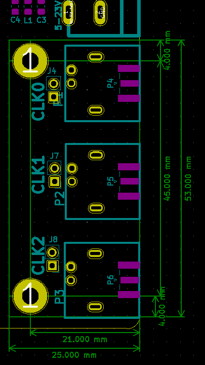
J4, J7, J8 - BNC/SMA input headers
- Connect here to use the BNC or SMA jacks on the rear (option)
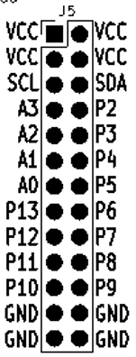
J5 - Arduino Pins
J6 - Voltage Adjustment
- Adjust voltage for 3.3V or 5V to match Pro Mini voltage before installing jumper
J9 - Use Raw Power
FTDI (on Arduino Pro Mini)
- Used to download program to Arduino Pro Mini
Human Interface (HID)
- Detachable board
- OLED
- Rotary Switch with Pushbutton
OLED
- 0.91" 128x32 or so rotary switch (installed in SW1 location) is to the right
- 0.96" 128x64 (rotated) with rotary switch (installed in SW1 location) below
- SSD1306 family of displays
- Connections to Arduino Pins
- A4/SDA
- A5/SCL
Rotary Encoder
- Connections to Arduino Pins
- A=P2
- B=P3
- Switch=P4
I/O Boards
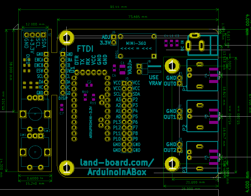
- Base board has 3 optional BNC (P1-P3) or edge launch SMA (P4-P6) connectors
- Brought to headers (J4, J7, J8)
- Easy to application specific custom I/O cards
- All Arduino pins brought to J5 - 2x13 pin header
- I/O pins are on 0.1" grid for easier prototyping
- P2-P13, A0-A3
- A4/A5 or SDA/SCL (connects to OLED)
- Location of mounting holes
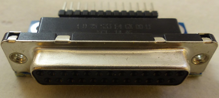
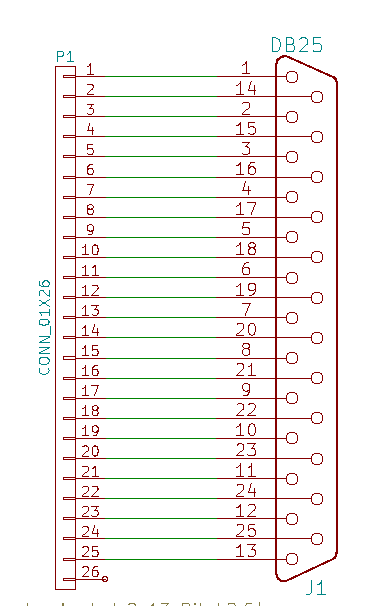
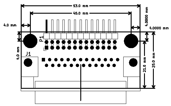
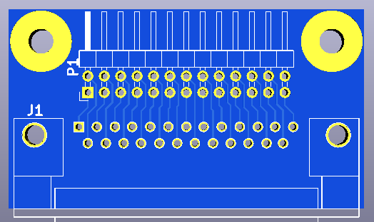
DB-25 Example
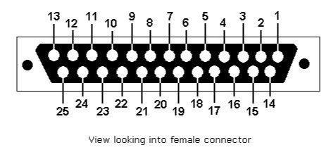
- Standard DB-25 female
- Does not have 26 pin of the 2x13 header in the box
- OK, extra powers/grounds at the ends
- Connect with 1:1 cables to 2x10/2x3 Dupont receptacles
- Does not have 26 pin of the 2x13 header in the box
Mechanicals/Enclosure
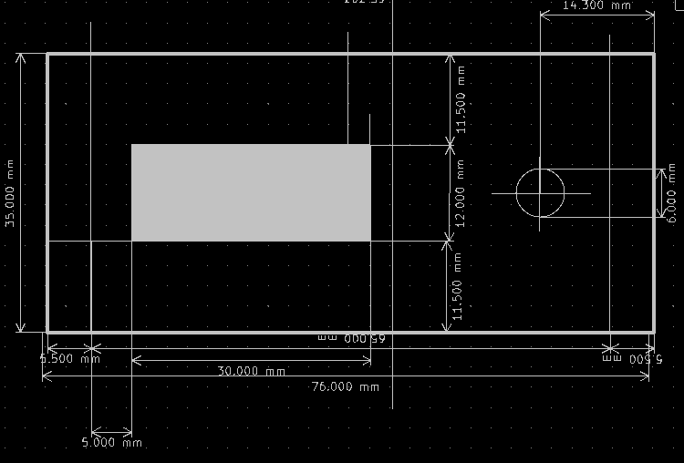
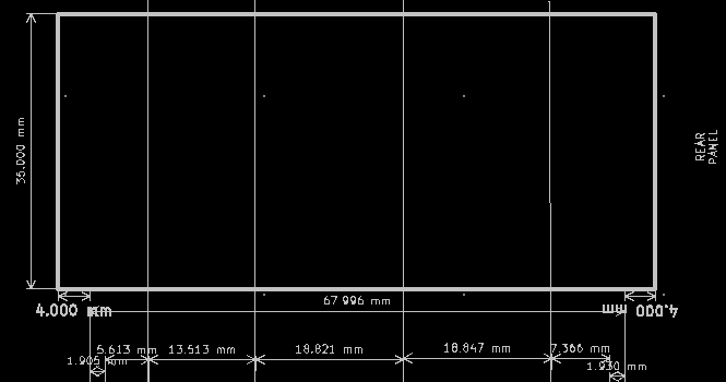
- Board is designed to fit into Aluminum Project Box Enclosure DIY 100*76*35mm - ebay search
Test
- Test code - OLED/Rotary Switch Test
- If there is no display on OLED, verify OLED appears at expected I2C address with I2C scan at I2C address 0x3C
- Expect results
Scanning...
I2C device found at address 0x3C  !
done
- May require a different constructor
- I used
U8X8_SSD1306_128X32_UNIVISION_HW_I2C u8x8(U8X8_PIN_NONE);
- Your mileage may vary
Software
GitHub Repository
- GitHub Repository
- OLED/Rotary Switch Test
- Rotary Encoder Tutorial - best code is at the ends under "Code For Improved Table Decode"
Total Memory usage with u8x8 Library and Rotary Encoder Code
- OLED/Rotary Switch Test
- Arduino bootloader uses up 2048 bytes of Flash
Sketch uses 7062 bytes (22%) of program storage space.
Maximum is 30720 bytes.
Global variables use 475 bytes (23%) of dynamic memory,
leaving 1573 bytes for local variables. Maximum is 2048 bytes.
Minimal u8x8 code
Sketch uses 6198 bytes (20%) of program storage space. Maximum is 30720 bytes. Global variables use 446 bytes (21%) of dynamic memory, leaving 1602 bytes for local variables. Maximum is 2048 bytes.
Download
- FTDI cable
- FTDI jumper is set to 3.3V
- Power wire is not used
- Other connections are 1:1
