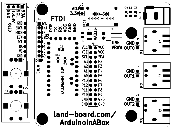
ArduinoInABox Assembly Instructions Rev 1
Jump to navigation
Jump to search
Parts List
| Item | Qty | Reference(s) | Value | Item | Qty | Reference(s) | Value | |
|---|---|---|---|---|---|---|---|---|
| 1 | 1 | C1 | 10uF | 9 | 2 | J2, J3 | Header, Straight or Right Angle, 1x8 | |
| 2 | 7 | C2-C8 | 0.1uF (0805) | 10 | 3 | J4, J7-J8 | Header, 1x2 (Note 1) | |
| 3 | 3 | R1-R3 | 10K (0805) | 11 | 1 | J5 | Header, Straight or Right Angle, 2x13 | |
| 4 | 2 | R10, R11 | 2.2K (0805) | 12 | 2 | J6, J9 | Header, Right Angle, 1x2 | |
| 5 | 2 | L1, L2 | Ferrite Bead (0805) | 13 | 1 | J99 | DC Jack | |
| 6 | 1 | J1 | OLED_I2C (0.91 or 0.96) | 14 | 3 | P1-P3 | BNC (Note 2) | |
| 7 | 1 | U1 | Arduino Pro Mini (3.3V or 5V) | 15 | 3 | P4-P6 | SMA (Note 3) | |
| 8 | 1 | SW1 or SW2 | Rotary Encoder w Switch |
Notes
Note 1: J4, J7 J8 connect to BNC or SMA connectors
Note 2: J6, J9 Power options
        Install J9 to use raw power from DC Jack
        Don't install MINI-360 if J9 is used
        Install J6 is Mini360 is used
        Adjust output voltage before installing J6 shunt
Note 3: On-board BNC or SMA connectors
        P1-P3 are BNC connectors
        Can use P4-P6 SMA instead
- Off-board output
- Use DB25-02 card for I/O
