Difference between revisions of "Screwduino"
Jump to navigation
Jump to search
Blwikiadmin (talk | contribs) |
Blwikiadmin (talk | contribs) (→Power) |
||
| Line 105: | Line 105: | ||
** Install jumper across the EXT pins to power the card from the DC jack. | ** Install jumper across the EXT pins to power the card from the DC jack. | ||
** Leave the jumper off when powering the card from the ISP connector. | ** Leave the jumper off when powering the card from the ISP connector. | ||
| + | |||
| + | == Factory Test Procedure == | ||
| + | <pre> | ||
| + | Remove power select jumper JP2 (install with 1 side of jumper on pin 1 and other side of jumper to air) | ||
| + | Disconnect USB cable from ISP programmer to power programmer off | ||
| + | Connect ISP cable to JP3 being careful to observe location of pin 1 (red power lead is at pin 2) | ||
| + | Program the Screwduino with UNO bootloader - verify it programs without error | ||
| + | Move power select jumper JP2 to USB pins | ||
| + | Attach FTDI to USB being careful to observe proper polarity of connector | ||
| + | Upload Screwduino Test Code | ||
| + | Attach LED with series resistor | ||
| + | Ground to GND connection in bottom right screw terminal | ||
| + | Move LED + side to terminal pins D3-D13 and A0-A5. LED should blink shortly at each position | ||
| + | Disconnect USB at FTDI | ||
| + | Install power select jumper JP2 on EXT pins | ||
| + | Apply 9V power to DC power jack using current limited power supply | ||
| + | Verify power is 5.0V +/- 0.1V at terminal block pins +5V and Ground | ||
| + | Verify LED lights briefly on terminal pins D3-D13 and A0-A5. LED should blink shortly at each position | ||
| + | Disconnect DC power jack | ||
| + | Move power select jumper JP2 to USB pins | ||
| + | Download Arduino minimal sketch via FTDI USB connector (not via programmer) | ||
| + | Part should program (this checks the D0 and D1 connections to the FTD)) | ||
| + | Remove power select jumper JP2 (install with 1 side of jumper on pin 1 and other pin to air) | ||
| + | Board ships with the power select jumper in the open position (for ISP programming) or USB (for FTDI) | ||
| + | </pre> | ||
== Assembly Sheet == | == Assembly Sheet == | ||
* [[Screwduino Assembly Sheet]] | * [[Screwduino Assembly Sheet]] | ||
Revision as of 13:56, 10 January 2020
Contents
Features
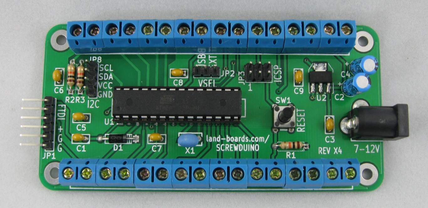
- Arduino UNO compatible
- Arduino UNO bootloader
- Select UNO in Arduino IDE to download card
- No USB connector/chip.
- Use a FTDI download cable or FTDI to USB interface for USB (not supplied)
- ICSP header for download
- 4-pin I2C connector for easy attachment of an I2C LCD display and other I2C sensors (like temperature sensors).
- Beware there are many different I2C pinouts.
- Added 10K ohm pullup resistors (R3 and R4) from the I2C SDA/SCL to +5V
- If the user doesn't want the resistors, they can snip them out of the circuit
- Uses through hole parts so that it is easier to assemble.
- The sole exception is the voltage regulator which is surface mount for heat transfer
- 5mm pitch screw terminal blocks.
- Reset switch.
- 7-12V DC on standard 2.1mm DC power connector
- Power selection jumper (FTDI, Regulator, Screw Terminals)
- Four (4) good mounting holes that take 4-40 screws and have more than enough clearance for screw heads, standoffs and/or nuts.
Design Advantages
Gets away from all of the painful wire jumpers and pins that constantly come loose. Makes the step from prototype to final design much easier.
| Method | Material Costs | Labor Tasks | Power/Ground pins | Wires secure? | Mounting | I2C Support |
|---|---|---|---|---|---|---|
| Processor | UNO - $30 | Strip wires and solder to parts | 3 GND1 PWR | Wires don't stay in holes with any stress. | Poor | No connector |
| Breadboards | Uno - $30 +Breadboard $10 | Strip wires or use breadboard wires | 120 each PWR/GND for 700 point breadboard | Moderately secure since the holes are usually “tight” | Poor | No connector |
| ProtoShields | Uno - $30 +Shields - $15 | Lot of time- consuming soldering of custom wiring | Vary but usually enough although maybe not connectorized in the best use | Wires typically soldered so secure | Poor | No connector |
| Sensor Shields | Uno - $30 +Shields - $15 | Use custom wires | Excellent at 1 per Arduino Digital/Analog pin | Connectors are secure | Poor | Yes |
| Screw Wings | Uno - $30 + Wing Shield - $15 | Strip wires and solder to parts | Varies depending upon shield | Connections very secure | Poor | No connector |
| Screwduino | $30 (est) | Strip wires and solder to parts | 5 – Ground 4 – PowerAdditional on other connectors | Connections very secure | Excellent | Yes |
Screwduino Schematic
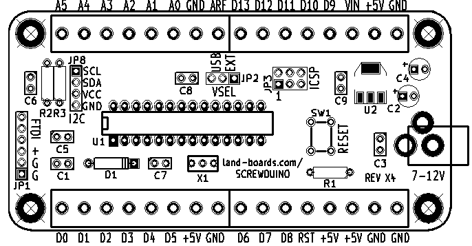
Screwduino Layout
Power
Measured 15 mA with 9V external power input (no loads but running program).
Card Power Source - VSEL Jumper
- This jumper selects the power source for the card
- Install jumper across the USB pins to power the card from the FTDI interface.
- Install jumper across the EXT pins to power the card from the DC jack.
- Leave the jumper off when powering the card from the ISP connector.
Factory Test Procedure
Remove power select jumper JP2 (install with 1 side of jumper on pin 1 and other side of jumper to air)
Disconnect USB cable from ISP programmer to power programmer off
Connect ISP cable to JP3 being careful to observe location of pin 1 (red power lead is at pin 2)
Program the Screwduino with UNO bootloader - verify it programs without error
Move power select jumper JP2 to USB pins
Attach FTDI to USB being careful to observe proper polarity of connector
Upload Screwduino Test Code
Attach LED with series resistor
Ground to GND connection in bottom right screw terminal
Move LED + side to terminal pins D3-D13 and A0-A5. LED should blink shortly at each position
Disconnect USB at FTDI
Install power select jumper JP2 on EXT pins
Apply 9V power to DC power jack using current limited power supply
Verify power is 5.0V +/- 0.1V at terminal block pins +5V and Ground
Verify LED lights briefly on terminal pins D3-D13 and A0-A5. LED should blink shortly at each position
Disconnect DC power jack
Move power select jumper JP2 to USB pins
Download Arduino minimal sketch via FTDI USB connector (not via programmer)
Part should program (this checks the D0 and D1 connections to the FTD))
Remove power select jumper JP2 (install with 1 side of jumper on pin 1 and other pin to air)
Board ships with the power select jumper in the open position (for ISP programming) or USB (for FTDI)


