FTDI-USB-TTL
Contents
Board Function
The FTDI USB to TTL Board allows a computer with a USB port to talk to devices (like Arduino derivatives) which have TTL-level (3.3/5V) serial ports.
USB-TTL-X6-2013-10-28.PNG
Features
The FTDI USB to TTL Board Revision X6 is a substantial departure from previous versions of the FTDI USB-to-TTL boards. Some of the differences include:
Different FTDI chip (FT230X instead of the FT232RL).
The FT230X[1] is less expensive ($2.04 at Mouser for a single piece) than the FT232RL[2] ($4.50 at Mouser for a single piece).
Smaller form factor.
Still 1" wide but narrower.
1" wide due to 4-40 hardware and USB connector.
Less expensive PWB (Under $1.10 a board from OSHPark).
Moved the connectors (USB and otherwise) to the back side of the board.
So the back is like the front except that the chip is on the other side of the board from the connector.
Moved the USB connector closer to the edge of the card.
This will help the connector stick through the side of the enclosure it is in more easily.
Set VCCIO to 3.3V so that the board can work with 3.3V or 5V interface cards.
3.3V or 5V input tolerant.
Board revision X5 had wrong pinout for the FTDI chip (QFN pinout instead of SO-16).
Rev X6 fixes that.
USB shell ground is no longer connected to the board ground.
Assuming that the USB cable is shielded (they are).
Assuming that the USB shield connects to the metal shell of the connector on both ends (they do).
Assuming that the USB cable doesn't connect the wire ground pin to the shield (they don't).
Don't know if this matters in plastic cases, but for metal cases it might matter since it will keep the grounds of the chassis isolated.
Handshake signals different but still work with Arduino IDE.
Uses RTS/CTS instead of DTR/CTS.
Pin 1's are marked with a white dot on the silkscreen.
Other important features include:
4-40 mounting holes on both sides of USB connector for sturdy mount.
3.3V/5V Header selects the voltage that will be provided from the FTDI USB to TTL Board.
Note that the 3.3V has serious current limitations since the FT230X provides the voltage regulation.
If the jumper is left off the header the board can provide its own power.
6-pin connector matches http://www.ftdichip.com/Products/Cables/USBTTLSerial.htm FTDI pinout for TTL connector</a>.
Transmit and Receive LED connector with current limiting resistor on-board.
5V tolerant inputs.
Why Make and not Buy?
All of the USB to TTL boards use the same [FTDI part] so they are all software/drivers compatible.
Nobody seems to have a great design for embedded use. Maybe there's not a huge market for embedded uses since the Arduino comes with a USB connector and by the time you add an external board you are right at the cost of the Arduino. But many of the derivatives are small form factor, or, like my designs the Screwduino, MiniDuino, and GVSDuino which has screw terminals, they have specific connection types and don't have the FTDI built onto the card.
Connectors - I like the WebUrban Olive board design. I bought two of them. They are great for desktop development. At $12 from a US company, you can't beat the deal.
But I don't particularly like the connectors on either end (or the converter in the middle). The USB side uses one of the large USB connectors and I'd prefer a smaller connector on the USB side. By the time you stack up the USB cable, the USB AM-BF converter and the card, you've got a pretty long chain. A [mini-B connector] would work better for embedded designs.
The other end of the WebOlive board has an 8-pin connector where they add two extra lines for LEDs. Not a bad idea for an embedded design, but something that you need to watch out for when plugging in a card to not misalign a shorter connector. And, if you wanted to use it for embedded LEDs, you'd still have to get power and ground for the LEDs from another connector. A 6 pin header would be best for the TTL serial end - maybe even a right angle male connector so that female to female cables can be used inside the embedded box.
Mounting Holes - Like the WebUrban board, most of the FTDI boards have no mounting holes. The ones that do are often pretty small. I would really like to be able to easily panel mount the board so it needs a pair of holes on the same side as the USB connector. The holes should be 4-40 for standard hardware and probably a mounting bracket.
Connector Pin-outs
H1 - Output Power Select Jumper
Jumper	Description
1-2	Provide +3.3V as VCC (current limited)
2-3	Provide +5V as VCC (limited to 1/2A USB current)
None	Do not provide any power on VCC
H2 - LED Header - 2x2 Header (Rev X5 and higher)
Pin	Description
1	TxLED+ Pull-up
2	TxLED-
3	RxLED+ Pull-up
4	RxLed-
J1 - USB connector (Mini-B type) - Standard Pinout
P1 - FTDI Connector (6-pin BERGSTIK)
FTDI Pinout
Pin	Description
Direction (Card Relative)
1	GND	Common
2	CTS	Input
3	VCC	Output
4	TX	Output
5	RX	Input
6	RTS	Output
USB Cable Pinouts
patillaje_conector_usb.jpg
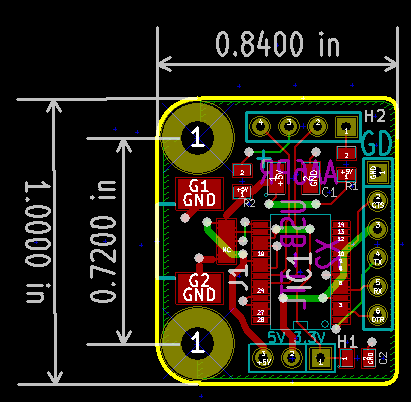
Board Layout Rev X6
FTDI-USB-X6-DimsInMM.PNG
USB-TTL-PWB-X6-2013-10-28.PNG
Previous Revisions
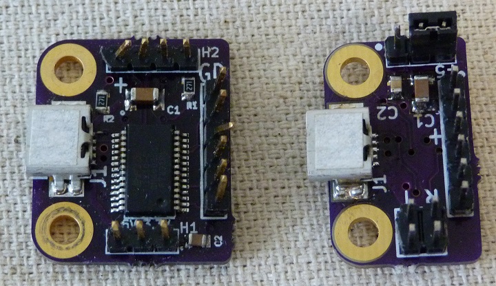
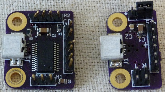
Rev X2 (left) and Rev X6 (right). The newer board moves the IC to the back side and reduces the board size.
Parts List (Rev X1-X4)
Descr	Qty	Footprint	RefDes	Mfg	MfgPN	Vendor	VendorPN
0.1uF	1	SM0805	C2	Murata	GRM155F51E104ZA1J	Mouser	81-GRM155F51E104ZA1J
10uF	1	SM1210	C1	Yaego	CC121ZKY5V8BB106	Mouser	603-CC121ZKY5V8BB106
270	2	SM0805	R1, R2	TE	CRG0805F270R	Mouser	279-CRG0805F270R
CONN_1	2	MTG-4-40	MTG1, MTG2	N/A	N/A	N/A	N/A
CONN_3	1	PIN_ARRAY_3X1	H1	FCI	68002-103HLF	Mouser	649-68002-103HLF
CONN_4	1	PIN_ARRAY_4x1	H2	FCI	68002-104HLF	Mouser	649-68002-104HLF
CONN_6	1	PIN_ARRAY-6X1	P1	FCI	68002-106HLF	Mouser	649-68002-106HLF
FT232RL	1	SSOP28	IC1	FTDI	FT232RL-REEL	Mouser	895-FT232RL
USB-B	1	J1	J1	Hirose	UX60SC-MB-5ST(80)	Mouser	798-UX60SC-MB-5ST80
Revision X2
Layout - Revision X2
Rev X2 H2 - LED connector - 4 pin 0.1" pitch header
Pin	Description
1	Pullup to +5V
2	LED0 (CBUS0)
3	Pullup to +5V
4	LED1 (CBUS1)
Change History
Revision X6
Corrected the pinout of the converter IC from QFN to TSOP. Board worked great after change.
Revision X5
Major Board Error - The PCB had the pinout for the QFN which is different than the TSOP. Board didn't work.
Revision X4
Skipped.
Revision X3
- Move USB further towards edge for case penetration
- Use 3.3V as VIO always rather than using jumper
Revision X2
- Rounded corners for host side can be placed up to corner with rounded insides.
Revision X1
- Initial Release


