Difference between revisions of "I2C-RPT"
Jump to navigation
Jump to search
Blwikiadmin (talk | contribs) |
Blwikiadmin (talk | contribs) |
||
| Line 27: | Line 27: | ||
* [https://github.com/land-boards/lb-Arduino-Code/tree/master/libraries/LandBoards_I2CRPT01 GitHub Repo] - Arduino Driver code | * [https://github.com/land-boards/lb-Arduino-Code/tree/master/libraries/LandBoards_I2CRPT01 GitHub Repo] - Arduino Driver code | ||
* [https://github.com/land-boards/lb-Arduino-Code/tree/master/LBCards/I2CRPT01 Github Repo] - Example code | * [https://github.com/land-boards/lb-Arduino-Code/tree/master/LBCards/I2CRPT01 Github Repo] - Example code | ||
| + | |||
| + | == Schematic == | ||
| + | |||
| + | * [http://land-boards.com/I2C-RPT-01/I2C-RPT-01_RevX3_Schematic.pdf Schematic] | ||
== Testing == | == Testing == | ||
Revision as of 17:37, 1 January 2020
Features
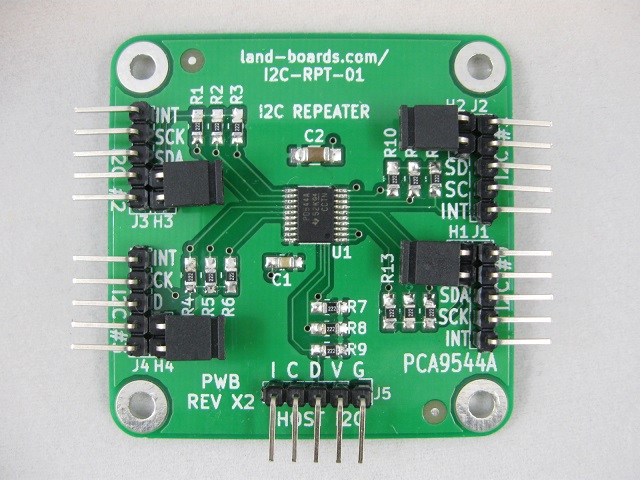
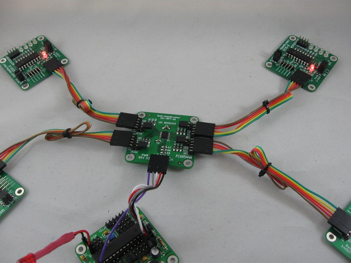
- I2C Hub / Repeater / Replicator / Multiplexer / De-multiplexer
- Four I2C Ports
- Host port Controlled via I2C
- PCA9544A IC Multiple vendors
- 3.3V or 5V host operation
- 3.3V or 5V slave ports operation
- Voltage translation between the ports
- Example: A Raspberry PI which runs 3.3V can control an I2C device which runs at 5V
- Interrupt line on each channel and host
- 100KHz/400KHz operation
- On-board termination resistors
- 49x49mm form factor
- 4 solid 4-40 mounting holes
- Arduino driver and example code
- Raspberry Pi example code
Drivers/Example Code
- GitHub Repo - Arduino Driver code
- Github Repo - Example code
Schematic
Testing
- Arduino Based Test Station
- Connects directly to I2C port on the Blue Pill Hub
- I2C address offset = 0x0
- Blue Pill Hub is set to offset=0x1 so it does not conflict
- Uses 4x of I2CIO-8 cards
- ODAS Tester Github Repo


