I2C-RPT
Jump to navigation
Jump to search
Contents
Features
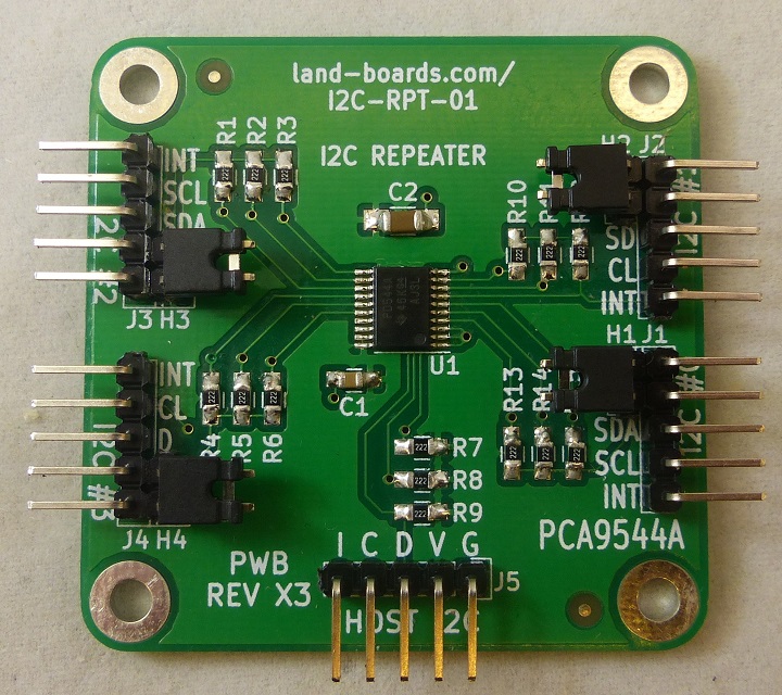
- I2C Hub / Repeater / Replicator / Multiplexer / De-multiplexer / Switch
- PCA9544A Datasheet IC Multiple vendors
- Four I2C Ports
- 100KHz/400KHz operation
- I2C Address fixed at 0x70
- Host port
- Controlled via I2C
- 3.3V or 5V host operation
- 3.3V or 5V slave ports operation
- Can power slave cards if they are at the same voltage
- 3.3V or 5V slave ports operation
- Removable jumper(s) to supply power from slave
- Voltage translation between the ports
- Example: A Raspberry PI which runs 3.3V can control an I2C device which runs at 5V
- Interrupt line on each channel and host
- On-board 2.2K termination resistors
- 49x49mm form factor
- 4 solid 4-40 mounting holes
- Drivers/Example Code
- Arduino driver and example code
- Raspberry Pi example code
I2C Termination Resistors
- Card has 2.2K Termination resistors on SDA/SCL lines
Headers
H1-H4 - Headers
- Jumpers
- H1 = I2C #0 Power
- H2 = I2C #1 Power
- H3 = I2C #2 Power
- H4 = I2C #3 Power
Power Options
- The card has flexible power options to power external I2C interfaces
- Power to the Host Interface comes in J5 Host I2C Interface
- This power can be used to drive external devices on the 4 I2C slave ports
Simple Method
- The "simplest" option is to provide power to the external I2C from the I2C-RPT-01 card
- Install jumper to power the particular I2C interface from the I2C-RPT-01 card
External Power
- External interface can also have independent power
- External interfaces can be at different voltage level from the I2C-RPT-01 card
- Example #1: Card Host voltage can be 5V (Arduino) and interface to 3.3V I2C interfaces
- Remove Jumper to power from external interface (3.3V or 5V)
- In this case, the terminators get pulled up from the external interface
- External interfaces can be at different voltage level from the I2C-RPT-01 card
Connectors
- 0.1" pitch connections
- Search ebay for Dupont headers
- Search ebay for Dupontwire jumper cable
- The slave I2C connectors are (4) 1x5 right angle 0.1" pitch headers
J1-J4 - I2C Slave ports
- Ports
- J1 = I2C Port #0
- J2 = I2C Port #1
- J3 = I2C Port #2
- J4 = I2C Port #3
- Pinout
- GND
- VCC (If Hx is installed, card powers this pin)
- SDA
- SCL
- INT*
J5 - I2C to/from Host port
- Power comes in this connector
- Voltage matches signal levels
- 2.2K Ohm terminated
- I2C address is fixed at 0x70
- GND (G)
- VCC (V) - Power into the card
- SDA (D)
- SCL (C)
- INT* (I) - Interrupt (active low)
Schematic
Testing
Test Station Hardware
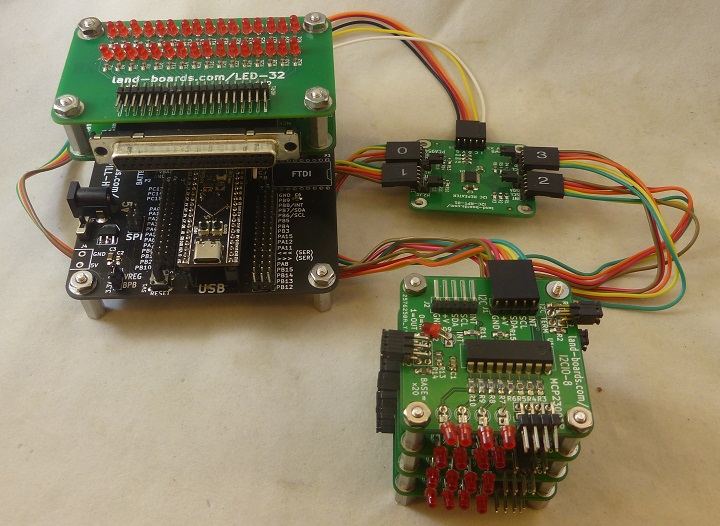
- Arduino Based Test Station
- Built in I2C mux on BLACK-PILL-HUB is set to offset=0x1 so it does not conflict with I2C address of UUT
- Cabling
- UUT J5 Host connects to I2C port (J7) on the BLACK-PILL-HUB
- UUT J5 Host INT pin connects via jumper cable to PB6-SIG
- Uses 4x of I2CIO-8 cards
- Cabling 5 wire from I2CIO-8 cards J1 to UUT I2C #0-#3
- Address jumpers are all installed for base address of 0x20
- On Unit Under Test (UUT)
- Card I2C address = 0x70
- Install H1-H4 shunts
- Powers I2CIO-8 cards from UUT
Test Procedure
- Run puTTY
- COM port from Device Manager
- 9600 baud
- No parity
- No handshake
- Menu will display
Checking if EEPROM is present on UUT...EEPROM is not present on UUT
Count of I2C devices in range 0x20-0x27 on UUT = 0
Found external I2C mux card
Select I2C Mux board type
1 - I2C-RPT-01 board
2 - I2C-RPT-08 board
- Enter 1
- Replies with
Init I2C-RPT-01 card
I2CIO8 card #0 was detected
I2CIO8 card #1 was detected
I2CIO8 card #2 was detected
I2CIO8 card #3 was detected
C=Card Tests, D=Direct, E=EEPROM, I=access Internal DIGIO32
- Verify that all 4 I2CIO-8 cards were detected
- Select C to test card
- Select B to bounce LED across LEDs on all 4 I2CIO-8 cards
- Verify all 16 LEDs blink
- Hit any key to stop blinking
- Hit T to test card
- Move jumper across I2CIO-8 card input jumpers
- Verify action on the screen
- Hit any key to stop test
- Mark TEST block on rear of card if passed
Test Station Software
I2C Timing
Drivers/Example Code
- GitHub Repo - Arduino Driver code
- Github Repo - Example code
- Raspberry Pi Example Code
Arduino Driver Functions
LandBoards_I2CRPT01(void) - Class Constructor
void begin() - Assumes I2C address = 0x70
void begin(uint8_t addr) - Offset address (adds base)
void setI2CChannel(uint8_t) - #defines are I2CRPT01_CH0 - I2CRPT01_CH3, I2CRPT01_NONE
uint8_t getI2CChannel(void)
uint8_t getIntStatus(void)
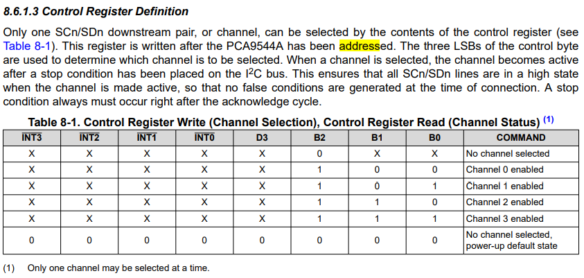
PCA9544 Control Register
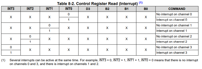
PCA9544 Status Register
Issues
Rev X3 Issues
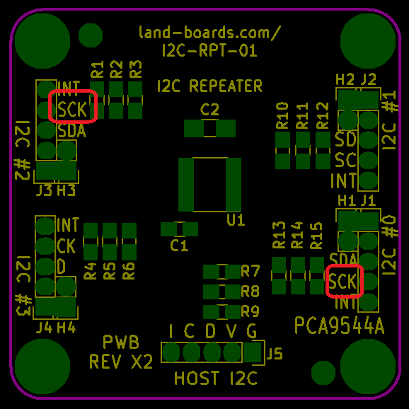
- Fixed SCK silkscreen to be SCL
- No issues found
Rev X2 Issues
- Board functions fine
- Silkscreen SCK should be SCL
Rev X1 Issues =
- SDA/SCL pins are swapped from "normal" pinout

