Difference between revisions of "SYNTH-MIXER6-01"
Jump to navigation
Jump to search
Blwikiadmin (talk | contribs) |
Blwikiadmin (talk | contribs) |
||
| (8 intermediate revisions by the same user not shown) | |||
| Line 3: | Line 3: | ||
* Eurorack 6HP | * Eurorack 6HP | ||
* Adapted from [https://note.com/solder_state/n/nffc1a33053be HAGIWO's 5 Channel Mixer Module] | * Adapted from [https://note.com/solder_state/n/nffc1a33053be HAGIWO's 5 Channel Mixer Module] | ||
| − | * Rear card is too tall to fit in rack between | + | * '''Rear card is too tall to fit in rack between rail''' |
| − | ** | + | * Hacksaw off top of card - remove J1, J2, RV1, RV2 to make 4 in mixer |
| + | ** Too tight at the bottom, need to hack off J2, RV2 | ||
| + | * Move up holes when mounting card to panel | ||
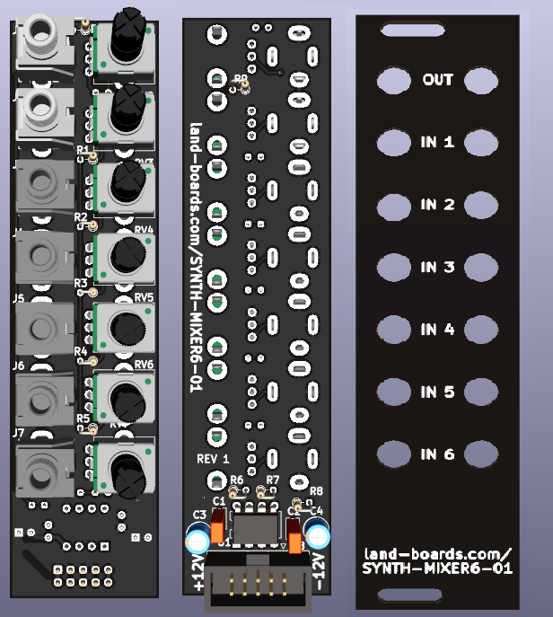
* Views: Front (controls), Parts side, Front Panel | * Views: Front (controls), Parts side, Front Panel | ||
| Line 13: | Line 15: | ||
=== Rev 1 === | === Rev 1 === | ||
| − | * Connector card is too big | + | * Connector card is too big to fit between mounting rails |
| − | ** | + | ** Hacksaw off J1/RV1 by clamming between boards in vice |
| − | ** | + | ** Sand end of board |
| + | ** Front and back fill are both GND on this card | ||
| + | ** Deletes J1, RV1, R9, R10 | ||
| + | ** Use RV7 as output pot | ||
| + | ** Use J7 as output jack | ||
** Cut S/S trace J7 to RV7 | ** Cut S/S trace J7 to RV7 | ||
| + | * Isolate J7 tip switch | ||
| + | ** Cut pin or isolate grounds on both sides | ||
| + | ** Do not install R6 | ||
| + | ** 1K from J7 (pin towards center of card to U2-7 | ||
| + | *** Use unused pad of R6 to route Kynar wire from top to bottom | ||
| + | * RV7 center goes to ground R6 pad | ||
* Should have put the pots on the left and jacks on the right | * Should have put the pots on the left and jacks on the right | ||
| + | * Re-label panel using P-Touch label | ||
| + | ** Cover OUT holes/silkscreen at top of panel | ||
| + | * Re-label IN6 as OUT | ||
| + | |||
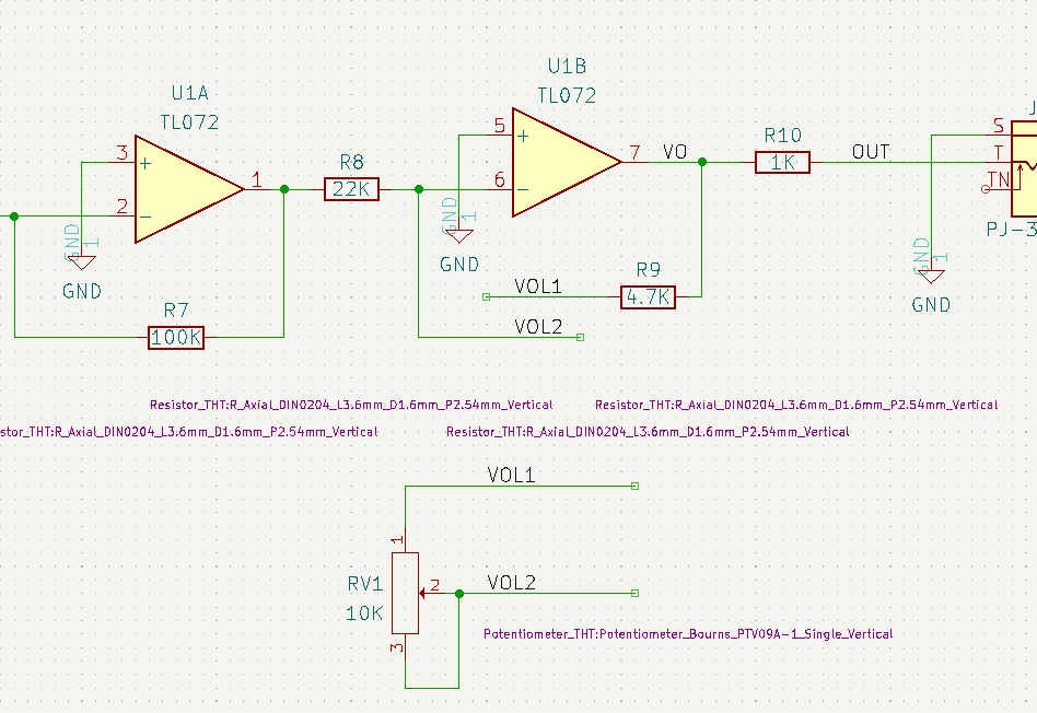
| + | [[FILE:SYNTH-MIXER6-01_Rework.PNG]] | ||
| + | |||
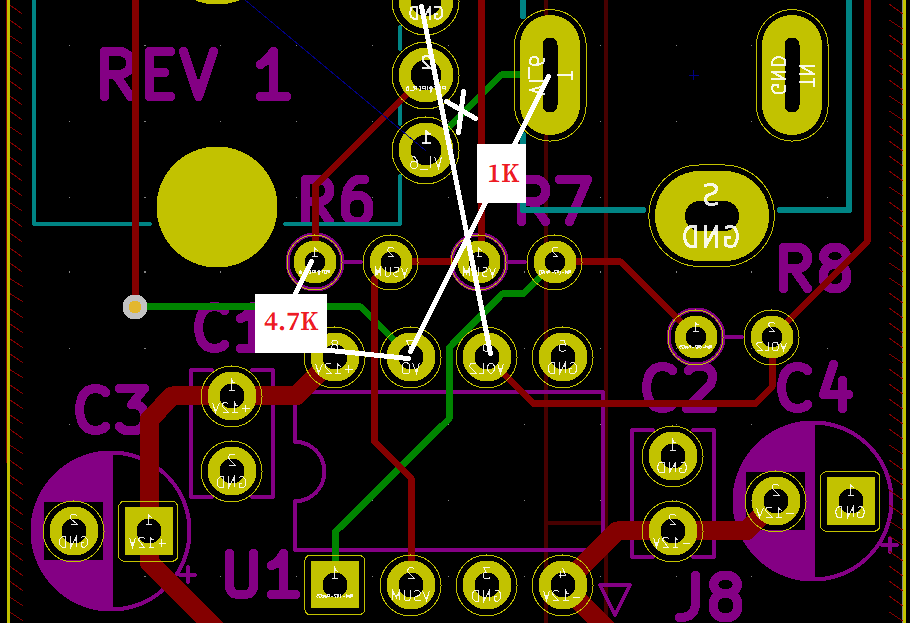
| + | [[FILE:SYNTH-MIXER6-01_Rework_PCB.PNG]] | ||
== Assembly Sheet == | == Assembly Sheet == | ||
* [[SYNTH-MIXER6-01 Rev 1 Assembly Sheet]] | * [[SYNTH-MIXER6-01 Rev 1 Assembly Sheet]] | ||
Latest revision as of 12:06, 18 October 2022
6 Channel Mixer
- Eurorack 6HP
- Adapted from HAGIWO's 5 Channel Mixer Module
- Rear card is too tall to fit in rack between rail
- Hacksaw off top of card - remove J1, J2, RV1, RV2 to make 4 in mixer
- Too tight at the bottom, need to hack off J2, RV2
- Move up holes when mounting card to panel
- Views: Front (controls), Parts side, Front Panel
Issues
Rev 1
- Connector card is too big to fit between mounting rails
- Hacksaw off J1/RV1 by clamming between boards in vice
- Sand end of board
- Front and back fill are both GND on this card
- Deletes J1, RV1, R9, R10
- Use RV7 as output pot
- Use J7 as output jack
- Cut S/S trace J7 to RV7
- Isolate J7 tip switch
- Cut pin or isolate grounds on both sides
- Do not install R6
- 1K from J7 (pin towards center of card to U2-7
- Use unused pad of R6 to route Kynar wire from top to bottom
- RV7 center goes to ground R6 pad
- Should have put the pots on the left and jacks on the right
- Re-label panel using P-Touch label
- Cover OUT holes/silkscreen at top of panel
- Re-label IN6 as OUT


