Difference between revisions of "ArduinoInABox"
Jump to navigation
Jump to search
Blwikiadmin (talk | contribs) |
Blwikiadmin (talk | contribs) |
||
| Line 32: | Line 32: | ||
*** When the pin is HIGH value, the LED is on, when the pin is LOW, it's off. | *** When the pin is HIGH value, the LED is on, when the pin is LOW, it's off. | ||
** 6 analog inputs | ** 6 analog inputs | ||
| − | * On-board | + | * On-board resonator (8 or 16 MHz) |
* Reset button | * Reset button | ||
* A six pin header can be connected to an FTDI cable provide USB power and communication to the board | * A six pin header can be connected to an FTDI cable provide USB power and communication to the board | ||
Revision as of 15:22, 8 May 2022
Contents
Features
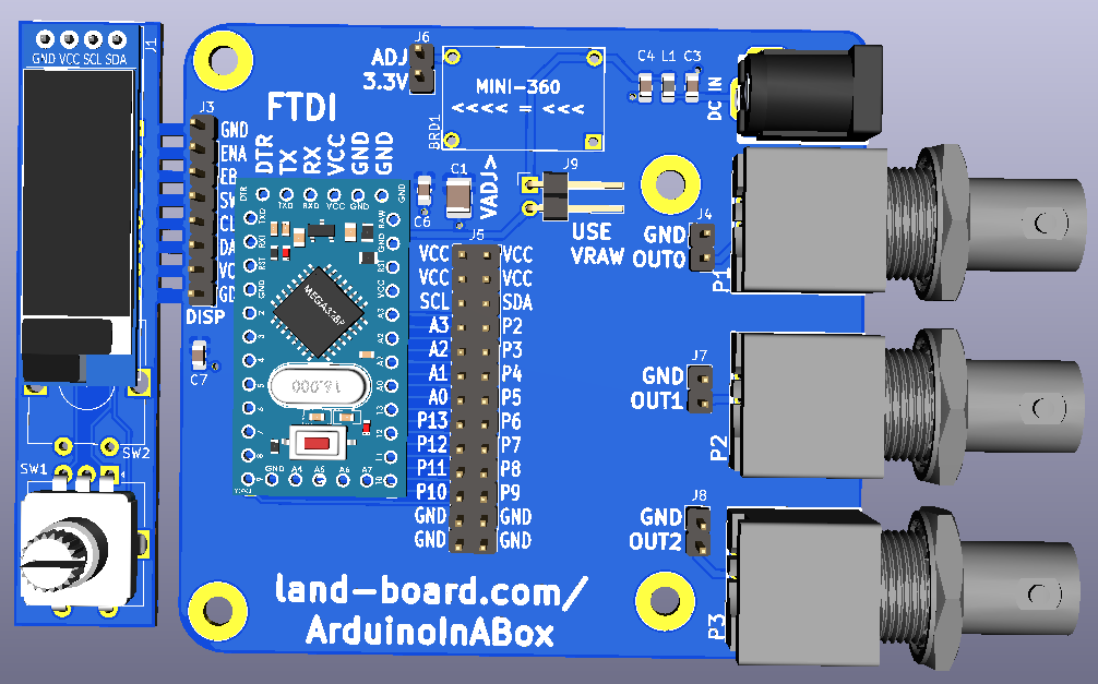
- Arduino Pro Mini
- Detachable Human Interface design (HID)
- Flexible Input power
- On-board DC/DC buck regulator allows 7-23V input
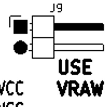
- Direct 7-9V input (USE VRAW jumper)
- 3.3V of 5V Arduino support
- I/O Boards
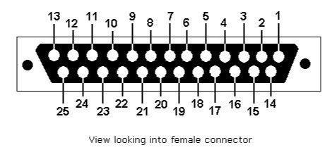
- DB-25
- Mounts in a standard extruded Aluminum enclosure
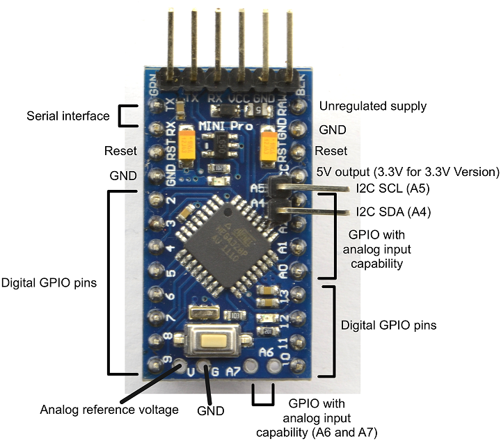
Arduino Pro Mini
- Inexpensive and widely available
- Arduino Pro Mini sCHEMATIC
- I/O - 14 digital input/output pins (of which 6 can be used as PWM outputs)
- Serial: 0 (RX) and 1 (TX).
- Used to receive (RX) and transmit (TX) TTL serial data.
- These pins are connected to the TX-0 and RX-1 pins of the six pin header.
- External Interrupts: 2 and 3.
- These pins can be configured to trigger an interrupt on a low value, a rising or falling edge, or a change in value.
- See the attachInterrupt function for details.
- PWM: 3, 5, 6, 9, 10, and 11.
- Provide 8-bit PWM output with the analogWrite function.
- SPI: 10 (SS), 11 (MOSI), 12 (MISO), 13 (SCK).
- These pins support SPI communication, which, although provided by the underlying hardware.
- LED: 13.
- There is a built-in LED connected to digital pin 13.
- When the pin is HIGH value, the LED is on, when the pin is LOW, it's off.
- 6 analog inputs
- Serial: 0 (RX) and 1 (TX).
- On-board resonator (8 or 16 MHz)
- Reset button
- A six pin header can be connected to an FTDI cable provide USB power and communication to the board
- 3.3 or 5V
- 8 MHz (3.3V) or 16 MHz (5V)
- Programmable in Arduino IDE
Detachable Human Interface design (HID)
- OLED
- 128x32 or 128x64
- u8x8 driver - 6.2KB overhead
- Rotary Encoder with switch
- Can leave attached to main board until installing in box
Input power
- Wide input voltage range
- 5-23V (for 3.3V Arduino Pro Mini)
- 7-23V (for 5V Arduino Pro Mini)
- 2.1mm DC Power Connector Jack
- RF filter into Switching regulator board
- 2nd RF filter into HID card
- Mini360 Switching Mode Power Supply
- About $1
- Jumper to use raw input and not populate the Mini360
- Uses the inputs jack as RAW power into the Arduino Pro Mini
- 3.35-12 V (3.3V model) or 5-12 V (5V model)
I/O Boards
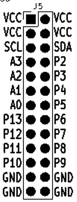
- Arduino pins brought to 2x13 header
- I/O pins are on 0.1" grid for easier prototyping
- P2-P13, A0-A3
- A4/A5 or SDA/SCL
- Easily designed
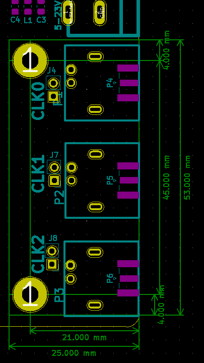
- 3 BNC or SMA connectors
- Brought to headers
- DB25 pass-through
Connectors
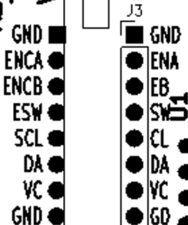
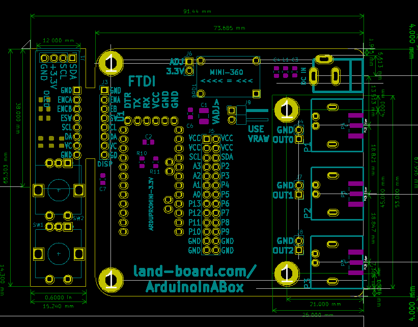
J2 - On HID
J3 - On base board
J6 - Voltage Adjustment
- Adjust voltage for 3.3V or 5V with jumper not installed
J5 - Arduino Pins
J9 - Use Raw Power
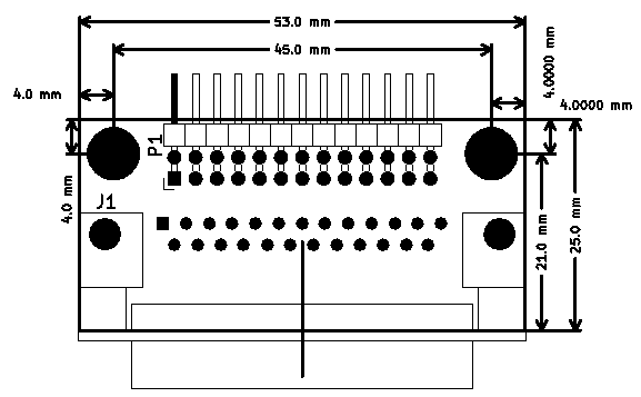
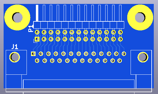
DB-25 Example
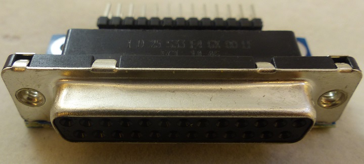
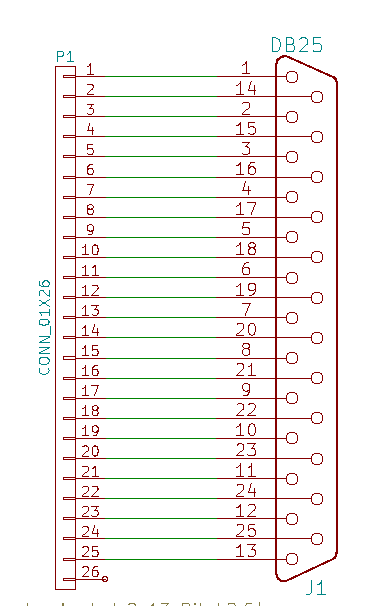
- DB25-02
- Standard DB-25 female
- Misses 1 pin of the 2x13 header in the box
- OK, extra powers/grounds at the ends
- Connect with 1:1 cables to 2x10/2x3 Dupont receptacles
Mechanicals/Enclosure
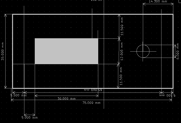
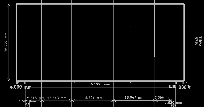
- Board is designed to fit into Aluminum Project Box Enclosure DIY 100*76*35mm - ebay search
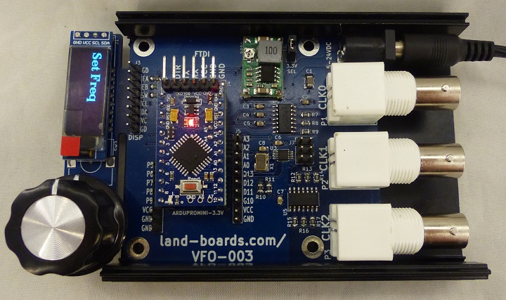
- VFO-003 - Similar in a box
Software
- GitHub Repository - VFO-003
- Minimal Viable Product build - GitHub repo
Memory Usage
- Minimal Viable Product Build - GitHub repo branch
- Arduino bootloader 2048 of Flash
- Display code: 10260 of Flash and 1033 of SRAM using u8g2
- Alternate display code: 6198 of Flash and 446 of SRAM using u8x8
- Si5351 code: 12076 of Flash and 378 of SRAM
Total Memory usage with u8g2 Library
Sketch uses 25970 bytes (84%) of program storage space. Maximum is 30720 bytes. Global variables use 1503 bytes (73%) of dynamic memory, leaving 545 bytes for local variables. Maximum is 2048 bytes.
Total Memory usage with u8x8 Library
- ~4K less than the u2g2 library
Sketch uses 22064 bytes (71% of program storage space. Maximum is 30720 bytes. Global variables use 925 bytes (45%) of dynamic memory, leaving 1142 bytes for local variables. Maximum is 2048 bytes.
Minimal u8g2 code
Sketch uses 10260 bytes (33%) of program storage space. Maximum is 30720 bytes. Global variables use 1033 bytes (50%) of dynamic memory, leaving 1015 bytes for local variables. Maximum is 2048 bytes.
- Code
void setup(void)
{
  u8g2.begin();

}

void loop(void)
{
  printStringToOLED("VFO-003");
}

void printStringToOLED(char * charStr)
{
  u8g2.clearBuffer();
  u8g2_prepare();
  u8g2.drawStr( 0, 0, charStr);
  u8g2.sendBuffer();
}

// u8g2_prepare()
// Setup the screen font, etc
// List of fonts
// https://github.com/olikraus/u8g2/wiki/fntlist8#u8g2-fonts-capital-a-height-38
void u8g2_prepare(void)
{
  u8g2.setFont(u8g2_font_t0_11b_tf); // 8 Pixel tall font
  u8g2.setFontRefHeightExtendedText();
  u8g2.setDrawColor(1);
  u8g2.setFontPosTop();
  u8g2.setFontDirection(0);
}
Minimal u8x8 code
Sketch uses 6198 bytes (20%) of program storage space. Maximum is 30720 bytes. Global variables use 446 bytes (21%) of dynamic memory, leaving 1602 bytes for local variables. Maximum is 2048 bytes.
- Code
// https://github.com/olikraus/u8g2/wiki/u8x8reference#c-example

#include <Arduino.h>
#include <SPI.h>
#include <U8x8lib.h>

#define U8X8_HAVE_HW_I2C

U8X8_SSD1306_128X32_UNIVISION_HW_I2C u8x8(U8X8_PIN_NONE);

void setup() {
  // put your setup code here, to run once:
  u8x8.begin();
}

void loop() {
  // put your main code here, to run repeatedly:
  u8x8.setFont(u8x8_font_victoriabold8_r);
  u8x8.drawString(0,0,"Hello World!");
  delay(1000);

}
