Difference between revisions of "QTPy49-01"
Jump to navigation
Jump to search
Blwikiadmin (talk | contribs) |
Blwikiadmin (talk | contribs) |
||
| Line 163: | Line 163: | ||
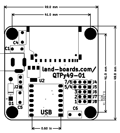
== Mechanicals == | == Mechanicals == | ||
| − | [[file: | + | [[file:QTPy49-01_MECHS.PNG]] |
== Assembly Sheet == | == Assembly Sheet == | ||
* [[QTPy49 Rev 1 Assembly Sheet]] | * [[QTPy49 Rev 1 Assembly Sheet]] | ||
Revision as of 17:01, 24 July 2022
Contents
Features
- CPU choices are
- QT Py (SAMD based)
- QT Py (RP2040 based)
- XIAO ESP32C3
- SeeedStudio XIAO ESP32C3 (New 2022-07)
- RISC-V Single Core
- Up to 160 MHz
- 400 KB SRAM
- 4 MB Flash
- 2.4GHz Wi-Fi subsystem
- Wiki
- ESP32C3 Datasheet
- Connectors/Headers
- SD card
- DC Power
- AD1 GVS
- AD2 GVS
- AD3 GVS
- I2C with ground/VCC
- TX/RX with ground/VCC
- QTPy49 can be powered from with either the USB C or DC jack
- Automatic Schottky diode power switching between
- 5V from USB C
- 5V on external DC jack
- 7-12V on DC jack
- Automatic Schottky diode power switching between
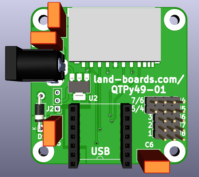
- 49x49mm ODAS form factor
- (4) 4-40 mounting holes
CPU Pinouts
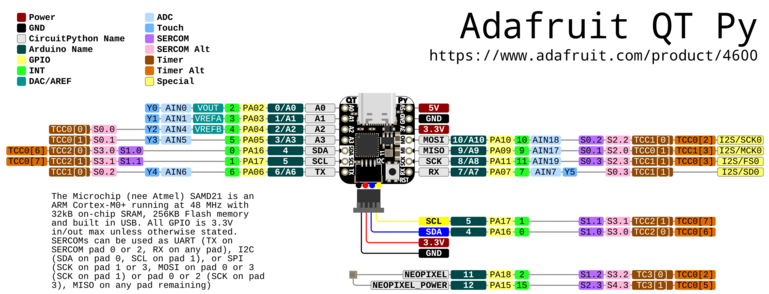
Adafruit QT Py SAMD
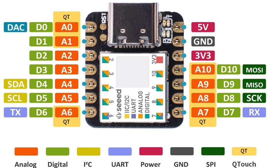
Seeed Studio XAIO SAMD
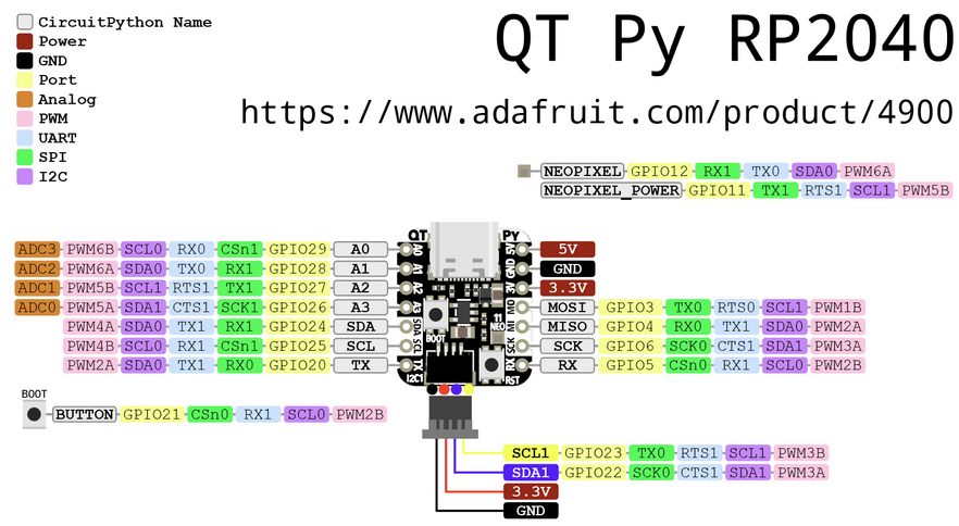
Adafruit QT Py RP2040
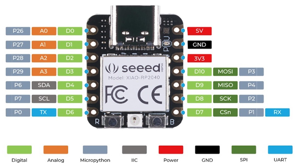
Seeed Studio XAIO RP2040
Connectors/Headers
- Ground, Voltage, Signal (GVS) connections
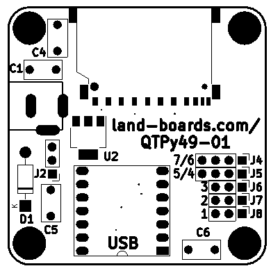
J1 - DC In
- QTPy49 can be powered from either the USB C or DC jack
- Automatic Schottky diode power switching
- Can use a regular Silicon Diode with sufficient current ex: 1N400X)
- 7-12V if regulator is installed
- 5V if regulator is not installed (install J2 jumper if not using regulator)
- Automatic Schottky diode power switching
- Center positive
J2 - Alt Power
- VREG (bottom pin)
- VIN
- GND (top pin)
J3 - SD Card
- MISO - GP4 (AD9)
- MOSI - GP3 (AD10)
- SCK - GP2 (AD8)
- SS - GP26 (AD0)
J4 - UART
- GND
- 3.3V
- TX, D6
- RX, D7
J5 - I2C
- GND
- 3.3V
- D4, SDA
- D5, SCL
J6 - AD3
- Digital I/O 3
- Analog In 3
- PWM output
- Capacitive touch input
- Pinout
- GND
- 3.3V
- AD3 (wired to J3-3)
J7 - AD2
- Digital I/O 2
- Analog In 2
- PWM
- Capacitive touch input
- Pinout
- GND
- 3.3V
- AD2
J8 - AD1
- Digital I/O 1
- Analog In 1
- Capacitive touch input
- AREF pin
- Pinout
- GND
- 3.3V
- AD1
MMBASIC XIAO RP2040 pin assignments
OPTION SERIAL CONSOLE COM1,GP0,GP1
OPTION SYSTEM SPI GP2,GP3,GP4
OPTION COLOURCODE ON
OPTION SDCARD GP26
Applications
Sample applications for the QTPy49 card.
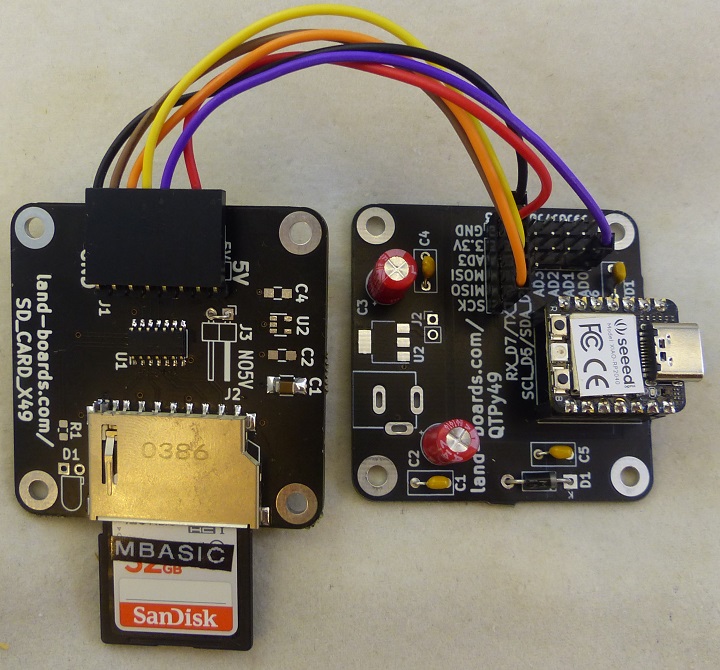
SD Card Loader
Prototype
- Built on QTPy49 and SD_CARD_X49 cards
- Can be powered from USB C connector or DC jack
