Difference between revisions of "ESP32-TERM"
Jump to navigation
Jump to search
Blwikiadmin (talk | contribs) |
Blwikiadmin (talk | contribs) |
||
| Line 321: | Line 321: | ||
* [http://www.fabglib.org FabGL] - ESP32 Display Controller and Graphics Library | * [http://www.fabglib.org FabGL] - ESP32 Display Controller and Graphics Library | ||
* [https://github.com/fdivitto/fabgl FabGL Github repo] | * [https://github.com/fdivitto/fabgl FabGL Github repo] | ||
| + | * [https://www.tindie.com/products/fabgl/fabgl-serial-terminal-ttl-and-rs232/ FabGL Serial Terminal - TTL and RS232] | ||
| + | ** Designed and built by FabGL author | ||
=== FabGL GPIOs assignment === | === FabGL GPIOs assignment === | ||
Revision as of 17:29, 29 August 2024
Contents
- 1 Features
- 2 Connectors
- 3 Software
- 4 Mechanicals
- 5 Assembly Sheet
Features
- ESP32 Module
- UART interface
- Keyboard/Mouse interface
- Drives VGA video
- Runs FabGL ANSI/VT Terminal firmware
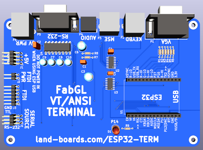
- "Typical" Serial Terminal Connectors
- Connectors down long side of the card
- VGA
- PS-2 keyboard
- PS-2 mouse
- Audio jack
- DE-9 Serial
- 5V DC on USB-B
- "Special" connectors
- Connectors down the short side
- Use with cards like SIMPLE-68008 which have FTDI connections
- FTDI connector - 6-pin
- 5V connector
- Programmable LED on P14
- 145x95mm size
- 135x85mm hole mounting spacing
- Can mount between 150x100mm (4"x6") clear acrylic sheets
- (4) 4-40 mounting holes
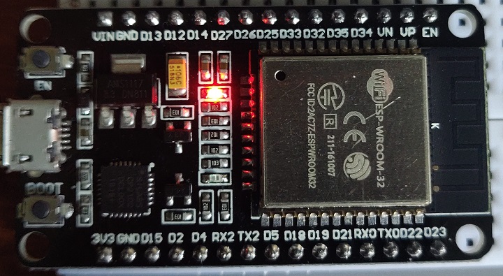
ESP-32 Module
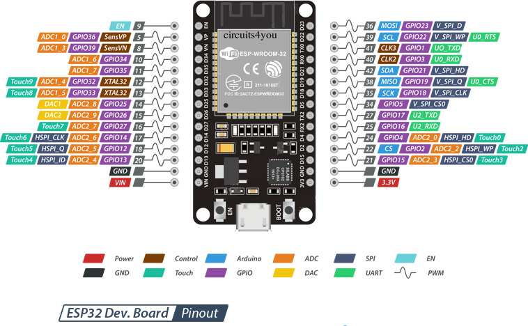
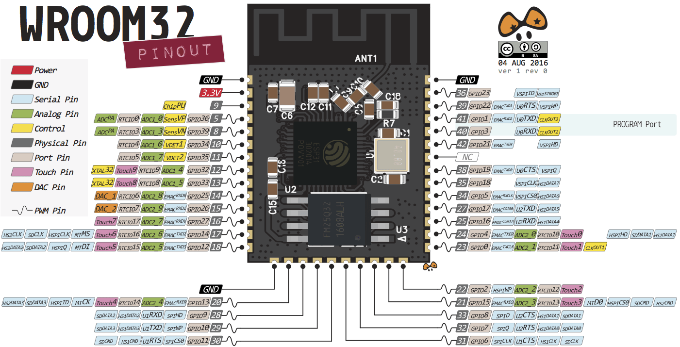
- Uses the ESP32 DevKit ESP32-WROOM GPIO Pinout
- On board Blue LED = Arduino Pin 2
- There are various modules out there with different pinouts, but this card uses this one
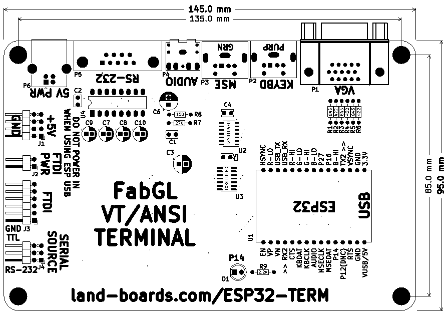
ESP-32 Module Pinout
"Chip" on the module
ESP32 Pin Usage
Module Features
- Architecture: Xtensa Dual-Core 32-bit LX6
- CPU frequency: up to 240MHz
- Total RAM available: 528KB (part of it reserved for system)
- BootROM: 448KB
- Internal FlashROM: none
- External FlashROM: code and data, via SPI Flash; usual size 4MB
- GPIO: 34 (GPIOs are multiplexed with other functions, including external FlashROM, UART, etc.)
- UART: 3 RX/TX UART (no hardware handshaking), one TX-only UART
- SPI: 4 SPI interfaces (one used for FlashROM)
- I2C: 2 I2C (bitbang implementation available on any pins)
- I2S: 2
- ADC: 12-bit SAR ADC up to 18 channels
- DAC: 2 8-bit DACs
- RMT: 8 channels allowing accurate pulse transmit/receive
- Programming: using BootROM bootloader from UART - due to external FlashROM and always-available BootROM bootloader, the ESP32 is not brickable
Connectors
P1 - VGA
- DB-15HD connector
- 64-colors (2:2:2)
- ESP32 pins
  HSync => GPIO23
  VSync => GPIO15
  R0    => GPIO22
  R1    => GPIO21
  G0    => GPIO19
  G1    => GPIO18
  B0    => GPIO5
  B1    => GPIO4
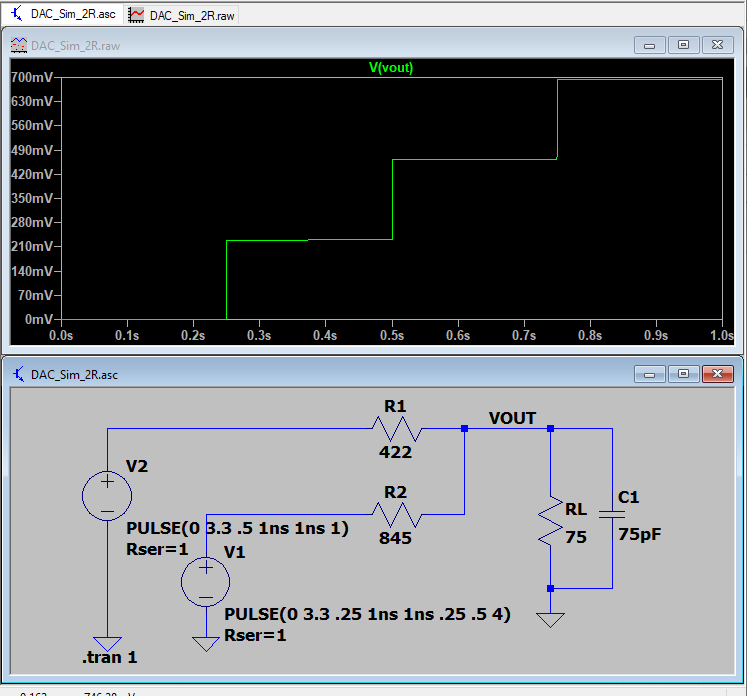
VGA - Resistor Selection
- ESP32 has a 3.3V driver which can drive more than 10 mA
- Ideal case drive current
- 0.7V (full scale VGA level) into 75 Ohms = 9.33 mA
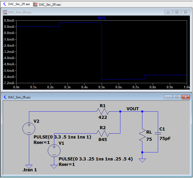
- 2/3 of the current or 6.16 mA comes from the lower value resistor (digital most significant bit)
- 1/3 of the current or 3.08 mA comes from the higher value resistor (digital least significant bit)
- R-2R values
- Ideal resistor values are 417.9 ohms and 835.7 ohms
- Standard value 1% resistors
- 1% standard values are 422 (Mouser), 845 (Mouser) Ohms
- Get closest values
- 0V, 0.228V, 0.460V, 0.693V
- Voltage steps are:
- Current steps are:
Video DAC LTSpice Simulation
- Video DAC Simulation files
- Video is 2:2:2 - R:G:B
Summing Video Resistor DAC
- Best values (1%)
- 422, 845
- 470, 820 are close/standard values
- 0.7V into 75 Ohm VGA load
- 3.3V drive
- ESP32 has 40 mA drive
- Uses 8 mA (max)
- Output in 4 equal voltage steps
P2 - PS/2 Keyboard
- Purple DIN 6 connector
- 5V power to the keyboard
- Shift 3.3V levels of the ESP32 to 5V of the keyboard/mouse
- ESP32 pins
  KBDAT   => GPIO32
  KBCLK   => GPIO33
P3 - PS/2 Mouse
- Green DIN 6 connector
- 5V power to the keyboard
- ESP32 pins
  MSEDAT   => GPIO27
  MSECLK   => GPIO26
P4 - Audio Out
- Mono output wired on both pins (ring/tip) of stereo 3.5mm Jack
- Line level outputs
- Requirs amplification
- ESP32 pins
AUD => GPIO25
P5 - RS-232
- On-board TTL to RS-232 converter
- Swings +/- 10V
- DB-9 Female
- DCE wiring
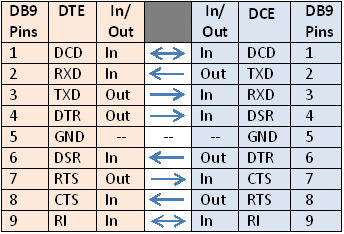
DCE - RS-232 Connections
- This card has a DCE connector
- The DCE (peripheral) has the female DB-9 connector
- The DTE (Host CPU) has the male DB-9 connector
- ESP-32 pins
  RX2    => GPIO34
  TX2    => GPIO2
  RTS    => GPIO13
  CTS    => GPIO35
P6 - 5V Power (USB)
- USB-B connector
- Power only (no data)
- Power can be sent out on J1 to external Processor card (like SIMPLE-68008 card)
J1 - 5V Power Header
- 2z3 right angle header
- Can be used for power in or out of the card
- Only one power source can be used with the card
J2 - FTDI Power in/out Header
- 1x2 right angle header
- Don't install jumper if an external FTDI interface with 5V power out is used
J3 - FTDI Header
- 1x6 right angle header
- Most recent (2020-02) ANSI terminal uses pin 34 for Rx
- Pinout
- GND
- RTS (from ESP32)
- 5V (Power in if J2 is installed)
- RX (to ESP32)
- TX (from ESP32)
- CTS (to ESP32)
- ESP32 pins
  RX2    => GPIO34
  TX2    => GPIO2
  RTS    => GPIO13
  CTS    => I35
Connections to SIMPLE-68008 Card
- 1:1 connection to SIMPLE-68008 Card
| ESP32-TERM | SIMPLE-68008 | |||
|---|---|---|---|---|
| Pin | Signal | Pin | Signal | |
| 1 | GND | 1 | GND | |
| 2 | RTS (out) | 2 | CTS (in) | |
| 3 | +5V | 3 | +5V | |
| 4 | RX (in) | 4 | TX (out) | |
| 5 | TX (out) | 5 | RX (in) | |
| 6 | CTS (in) | 6 | RTS (out) |
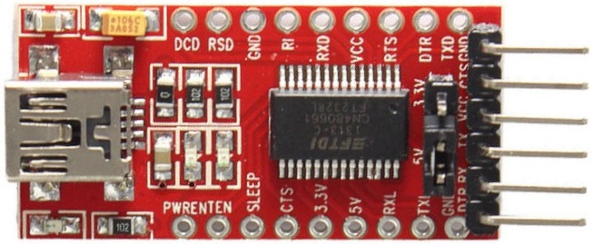
Connect to FTDI card
- Set FTDI jumper to 5V (image below shows jumper set to 5V)
J4 - Serial Source Selection Header
- 2x3 header
- Select either RS-232 connector or FTDI connector
- Silkscreen shows the appropriate side
- Both left for TTL level signals (via FTDI connection)
- Both right for RS-232 level signals
Software
- FabGL ANSI Terminal
- Using ANSI/VT Terminal for the ESP32 application
- Programmed using Arduino IDE
FabGL Libraries
- FabGL - ESP32 Display Controller and Graphics Library
- FabGL Github repo
- FabGL Serial Terminal - TTL and RS232
- Designed and built by FabGL author
FabGL GPIOs assignment
  VGA
    HSync => IO23
    VSync => IO15
    R0    => IO21
    R1    => IO22
    G0    => IO18
    G1    => IO19
    B0    => IO4
    B1    => IO5

  Audio
    AUD   => IO25

  PS/2 - Keyboard
    DAT   => IO32
    CLK   => IO33

  PS/2 - Mouse (Not used)
    DAT   => IO27
    CLK   => IO26

  UART - UART2
    RX    => IO34
    TX    => IO2
    RTS   => IO13
    CTS   => I35
FabGL Arduino library
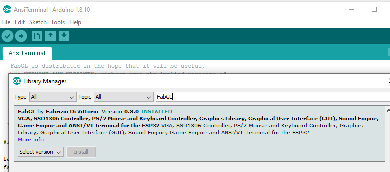
- Using FabGL library v1.0.9
Using Latest FabGL builds (not necessary to run the ANSITerminal)
- Fabrizio does a nice job of keeping his Arduino libraries up to date but if you want a bleeding edge experience, you can download his code from GitHub. Note, he's in active development so things often change.
Here's how I did it
- Install drivers via Arduino from the Library Manager
- These are not necessarily the latest files
- Move the FabGL from the Arduino libraries file folder to the desktop
- Copy the FabGL from the GitHub download to the Arduino files folder (where you removed the other folder)
- Examples will now be the latest.
- Compile/download/test the new files. You know it works if you now get sound from Space Invaders.
- Save as where you would normally save your Arduino sketches.
Arduino Programming
- Installing the ESP32 Board in Arduino IDE (Windows, Mac OS X, Linux)
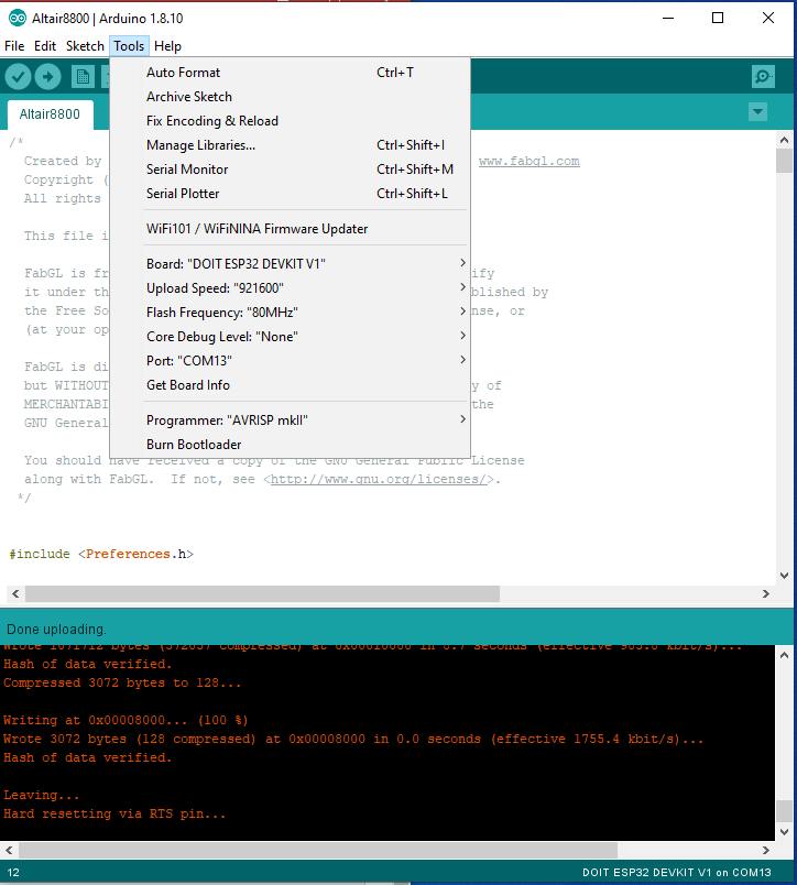
- Select the board : DOIT ESP32 DEVKIT V1
- Select the application
- File, examples, FabGL, examples, VGA, AnsiTerminal
- You may have to remove the module from the card to program it
- Pins on the card collide with download
- If you try to upload a new sketch to your ESP32 and you get this error message “A fatal error occurred: Failed to connect to ESP32: Timed out… Connecting…“. It means that your ESP32 is not in flashing/uploading mode
- You will need to press the boot button on the ESP32 module and release it after the Connecting message appears in the IDE
- Press the “Upload” button in the Arduino IDE to upload your sketch
- After you see the “Connecting….” message in your Arduino IDE, release the finger from the “BOOT” button:
Other Builds
- ESP32 ALTAIR EMULATOR GETS SPLIT PERSONALITY - Hackaday page
