Difference between revisions of "PROTO16-I2C"
Jump to navigation
Jump to search
Blwikiadmin (talk | contribs) |
Blwikiadmin (talk | contribs) |
||
| Line 1: | Line 1: | ||
[[File:tindie-mediums.png|link=https://www.tindie.com/products/land_boards/16-bit-digital-io-w-proto-area-proto16-i2c/]] | [[File:tindie-mediums.png|link=https://www.tindie.com/products/land_boards/16-bit-digital-io-w-proto-area-proto16-i2c/]] | ||
| + | |||
| + | <video type="youtube">E36qUUt2tQ</video> | ||
== 16-Bit Digital I/O Card with Prototyping area == | == 16-Bit Digital I/O Card with Prototyping area == | ||
Revision as of 12:10, 20 May 2022
Contents
16-Bit Digital I/O Card with Prototyping area
Features
- 16-bit Digital I/O card
- MCP23017 16-bit I2C I/O Expander
- Strong library support for all major microprocessors for MCP23017
- I2C Interface - Two Wire Interface
- Can run at 400 KHz or faster
- I/O Connector is inexpensive/standard DB-25
- Fuse protected power output on DB-25 with jumper bypass
- Large prototyping area
- Connections at edges to DB-25 and GPIO lines
- EEPROM for board ID and application specific information
- Write Enable jumper protects against accidental writes
- Open Data Acquisition System (ODAS) form factor (width is 95 mm)
- Host connectors
- Daisy-chain I2C connector
- Address select jumper
- Expandable I2C via I2C-RPT - I2C Repeater
- Interrupt out/Card Present
- Power connector (not required for minimal loads)
- Reversible pinout for safety
- I2C Termination jumpers for end of I2C chain
- Power can be 3.3V or 5V
- 95mm wide Open Data Acquisition System format
- 6-32 Mounting holes
Prototyping Area
- Large prototyping area
- Ideal for through-hole ICs
- Extra I/O Rows on both sides
- One side connects to DB-25 connector
- Other side connects to MCP23017 pins
- Prototyping area in the center of the card with power/ground bus up the middle two pins
- Easy connection to IC Power/Grounds
- Silkscreen on both sides of the card
File:PROTO16-protoarea-I2C.PNG
- The above is the top two rows of the prototyping area
- The pins on the far left are the pin number of the DB-25 connector (ex: Pin 24 is the top left, and pin 11 is in the next row).
- The next 3 pins are bussed across to each other (the same row)
- The next column has GND in all column positions
- The next column has VCC in all column positions
- The next 3 pins are bussed across to each other (the same row)
- The far right pin has the DIGIO part connections (blank for the first row and Digital I/O pin 8 in the next point).
Connectors
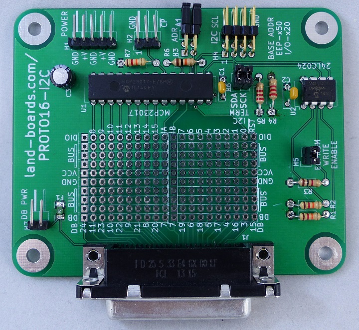
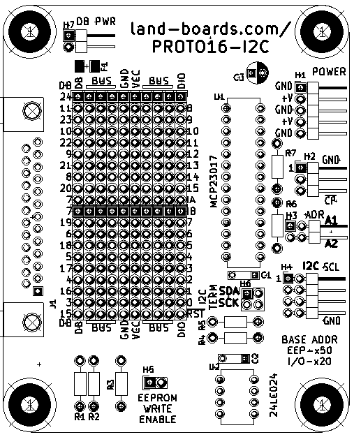
H1 - Power
- Connector is 1x5 of 0.1" header
- Connector is reversible
- Connector is optional since power can also be brought in via the I2C connector
- GND
- PWR
- GND
- PWR
- GND
H2 - Interrupt/Card Present Flag
- GND
- INT0*
- CARD_PRESENT* (Low if card is present, should be pulled up by Host card)
H3 - Address Select
- Sets the I2C offset address of the card
- Three bit address A1, A2
- A0
- A1
- A2
H4 - I2C
- Connector is 2x5 of 0.1" header
- Intended to be used for I2C daisy-chain of 4-pin cabling
- Power can be attached to the connector or power can be provided to the card via the J1 power connector
- May still want to connect ground
- SCL
- SDA
- VCC
- GND
H5 - EEPROM Write Enable
- Install to allow writes to EEPROM
- Remove to prohibit writes to EEPROM
H6 I2C Termination
- Two of two position headers
- Install headers in each position to terminate I2C line
- There should only be one I2C termination and it should be at the end of the I2C line
J1 - DB-25 I/O Connector
- Pins 1, 2, 14 are connected to Ground
- Pins 12, 13, 25 are connected to Power
- Pins 3-11 and 15-24 are connected to the Prototype area and are labeled on the PCB
MCP23017 Drivers
There are quite a I2C drivers for every major microcontroller (Arduino, Raspberry Pi, BeagleBone, etc).
Arduino Drivers
- Land Boards Arduino Driver Code/Example Software for the PROTO16-I2C Card
- Adafruit MCP23017 Arduino Driver
Raspberry Pi Drivers
BeagleBone Black Drivers
ESP32 MicroPython Drivers
PyBoard MicroPython Drivers
Linux Drivers
EEPROM
- 24LC024 EEPROM
- 2kbit
- I2C Serial EEPROM
- Wide Voltage range (1.8V to 5.5V)
- 400 KHz operating range
- 10 mS write cycle time
- EEPROM has a board ID
Factory Acceptance Tests
Setup
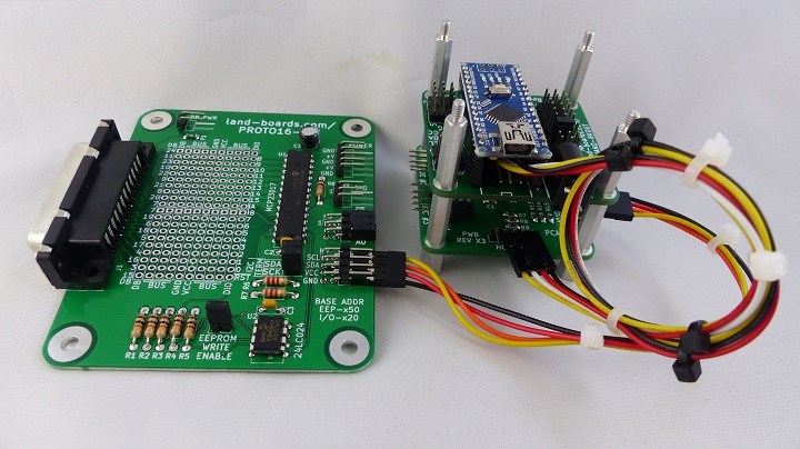
- Runs ODAS Card Test Software on Arduino Nano NANO-BKOUT with I2C-RPT card
- USB running puTTY
- 9600 baud
Program Personality EEPROM
- Menu driven
- Auto-detects card
- If test has been run before
Checking EEPROM for board type...Detected PROTO16-I2C board
R=Read EEPROM, W=Write EEPROM, T=Test DIGIOs, L=Loop Test, B=Bounce LEDs
- Presents card type list for un-programmed EEPROMs
Checking EEPROM for board type...Company Mismatch
Select the board type
1 - DIGIO16-I2C board
2 - DIGIO-128 board
3 - OptoIn8-I2C board
4 - OptoOut8-I2C board
5 - DIGIO32-I2C board
6 - PROTO16-I2C board
7 - ODAS-PSOC5 board
8 - TBD board
9 - TBD board
Select board >
- Select board
Select board > 6
Writing EEPROM
Initializing eep buffer
len of buffer=96
reading block
Family=ODAS
Company=land.boards.com
Product=PROTO16-I2C
Run I2C Loopback Tests
- Test 'T'
Loopback Test PASS = 1, FAIL = 0
Run Bouncing LEDs
- Select B
Bouncing LEDs - any key to stop
- Use LED card
Issues with Rev X1 board
Add A0 jumper for EEPROM and MCP23017 Verified works in Rev X2 (Kickstarter)


