Difference between revisions of "RPI-CONSOLE-U"
Jump to navigation
Jump to search
Blwikiadmin (talk | contribs) |
Blwikiadmin (talk | contribs) (→Specs) |
||
| Line 77: | Line 77: | ||
26-pin stacking connector | 26-pin stacking connector | ||
40-pin stacking connector | 40-pin stacking connector | ||
| − | External links | + | |
| + | == External links == | ||
| + | |||
Adafruit tutorial | Adafruit tutorial | ||
NOOBS without a display | NOOBS without a display | ||
How COM Ports Are Allocated On Driver Installation | How COM Ports Are Allocated On Driver Installation | ||
| − | Assembly Sheet | + | |
| + | == Assembly Sheet == | ||
| + | |||
RPI-CONSOLE Assembly Sheet | RPI-CONSOLE Assembly Sheet | ||
| − | Rev X3 (vs X2) | + | |
| − | Moved "Power Pi from USB" connector to center of card | + | == Rev X3 (vs X2) == |
| − | Rev X2 (vs X1) | + | |
| − | Moved connector slightly closer to the edge | + | * Moved "Power Pi from USB" connector to center of card |
| − | Made USB connector PWB pads longer | + | * Rev X2 (vs X1) |
| − | Rev X1 Checkout | + | * Moved connector slightly closer to the edge |
| − | Micro USB mounting holes fit well | + | * Made USB connector PWB pads longer |
| − | Connector could be slightly farther to the edge | + | |
| − | USB connector PWB pads were too short - trimmed pins to fit | + | == Rev X1 Checkout == |
| − | Ordered 3 more from OshPark new X2 rev | + | |
| + | * Micro USB mounting holes fit well | ||
| + | * Connector could be slightly farther to the edge | ||
| + | * USB connector PWB pads were too short - trimmed pins to fit | ||
| + | * Ordered 3 more from OshPark new X2 rev | ||
== Assembly Sheet == | == Assembly Sheet == | ||
* [[RPI-CONSOLE-U Assembly Sheet]] | * [[RPI-CONSOLE-U Assembly Sheet]] | ||
Revision as of 13:10, 24 January 2020
Contents
Features
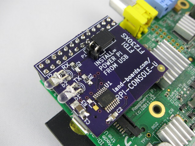
- Console port lets you talk to your Raspberry Pi over USB without a keyboard/mouse/monitor or Ethernet connection.
- 115200 baud
- USB Micro-B connector
- Mounted on the bottom of the card
- See also our USB Mini connector version
- Real FTDi FT230XS
- Jumper selectable - power the Pi from your computer's USB port.
- Some nwere Pi cards may take too much power
- Transmit/receive LEDs
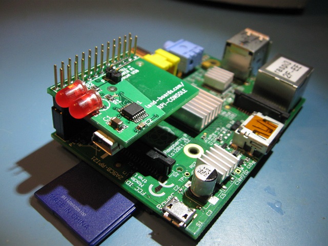
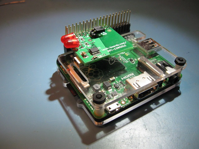
- 26-pin connector works with Model A and Model B Pis
Options
Extended 26-pin Connector
From RPI-CONSOLE page
Extended 40-pin Connector
From RPI-CONSOLE page
Low profile 26-pin Connector
Driver
Prototype Qualification Tests
Factory Acceptance Tests
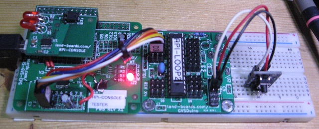
Test Procedure
- Test setup as above
- Test setup powered down
- Install UUT (RPI-Console card being tested)
- Disconnect USB cable to Arduino (not used for power)
- Install P1 jumper on UUT (power the test station from the RPI-CONSOLE)
- Connect USB cable from Test Computer (laptop) to UUT
- Boards should power up
- Run putty on Test Computer (laptop)
- Look in Device manager to make sure COM port was added
- Select COM port in putty
- Hit reset on Arduino Shield or attached to GVSDuino
- Verify the message comes back
The quick brown fox jumped over the lazy dog
0123456789
asdfghjkl
Hit keys to test
- Type and verify that the character comes back
- Disconnect USB to RPI-Console
Specs
26-pin stacking connector 40-pin stacking connector
External links
Adafruit tutorial NOOBS without a display How COM Ports Are Allocated On Driver Installation
Assembly Sheet
RPI-CONSOLE Assembly Sheet
Rev X3 (vs X2)
- Moved "Power Pi from USB" connector to center of card
- Rev X2 (vs X1)
- Moved connector slightly closer to the edge
- Made USB connector PWB pads longer
Rev X1 Checkout
- Micro USB mounting holes fit well
- Connector could be slightly farther to the edge
- USB connector PWB pads were too short - trimmed pins to fit
- Ordered 3 more from OshPark new X2 rev


