PicoVGA01
PicoVGA
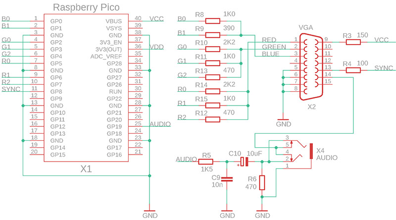
PicoVGA uses a Raspberry Pi Pico to drive a VGA/TV display. PicoVGA was designed by Miroslav Nemecek.
The RP2040 processor contains 264 KB of RAM. This is not much for higher resolution image output and therefore RAM needs to be very sparing. In technical practice and for retro games (the processor does not have the power for more advanced games), 8-bit graphics output in R3G3B2 format (i.e. red 3 bits, green 3 bits and blue 2 bits) is fully sufficient. Output in 16 or 24 bits is not meaningful in normal practice, as the Raspberry Pico does not have enough memory or power to provide such large amounts of data in areas other than short demos. Using the dithering technique, interesting display results can be achieved even with 8-bit output.
Software
The PicoVGA library is written in C/C++ and allows output from the Raspberry Pico to a VGA monitor or PAL/NTSC TV, with a focus on ease of use in technical and gaming applications. It provides 4 graphic overlay layers with transparency, nearly 30 frame buffer formats that can be freely combined with each other, making do with limited RAM memory size. The limitation of output to 8 bits also contributes to RAM saving.
Features
- 1 base layer and 3 overlay layers with transparency
- 8-bit output in R3G 3:3:2 format
- VGA progressive output up to 1280x960 resolution
- TV output in PAL or NTSC interlaced mode
- 30 frame buffer formats: graphics, tiles, text, special
- Colour palettes
- Screen split into segments of different formats
- RLE compression
- Transparency with selectable key colour
- Hardware sprites
- Output layers to different color bits (color planes)
- Automatic configuration video mode timings
- Automatic overclocking of processor
- Library uses the 2nd core, main program uses 1st core
- PWM mono audio output
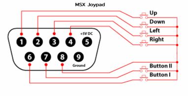
- Joystick connector(S)
Connectors
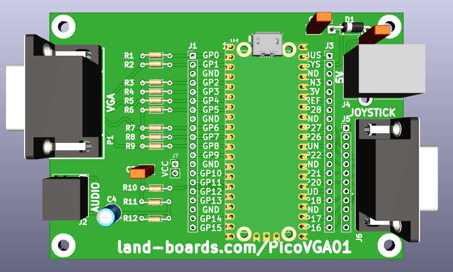
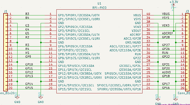
J1/J3 Pico breakout
J2 - Mono Audio
J4 - 5V USB B
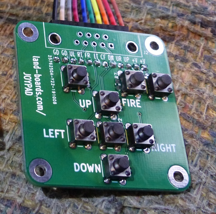
J5 - Joystick
- 1x12 Header matches pinout of JOYPAD card
// Init the JoyPad pins
// #define PB_UL 16		// Upper Left pushbutton
// #define PB_RT 17		// Right direction
// #define PB_FR 18		// Fire
// #define PB_LT 20		// Left direction
// #define PB_CF 21		// Center Fire
// #define PB_DN 22		// Down direction
// #define PB_UR 26		// Upper right
// #define PB_UP 27		// Up direction
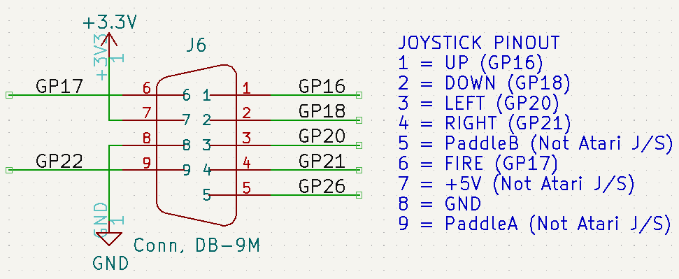
Joystick (DB-9)
- UP
- DOWN
- LEFT
- RIGHT
- +VCC
- BUTTON I
- BUTTON II
- BUTTON COMMON
- GND
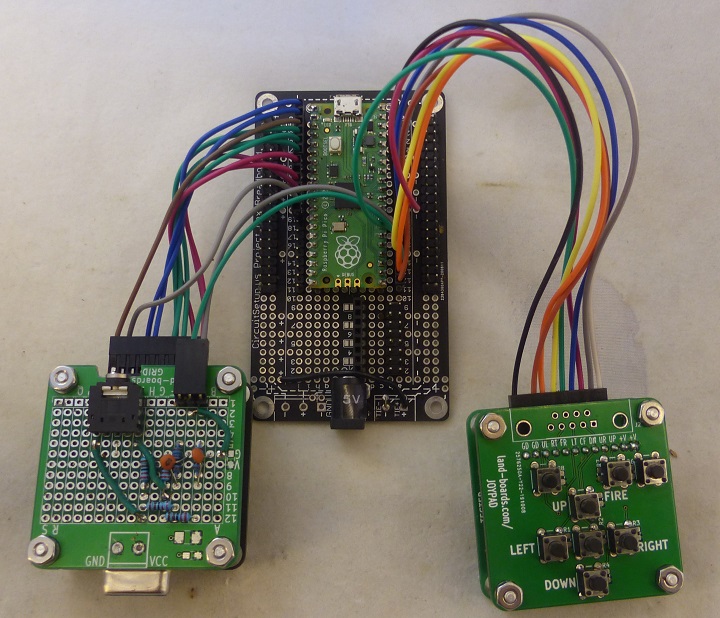
Prototype Build Hardware
- Uses cards
- Raspberry Pi Pico Breakout Board
- Raspberry Pi Pico
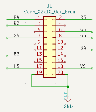
- VGAX49
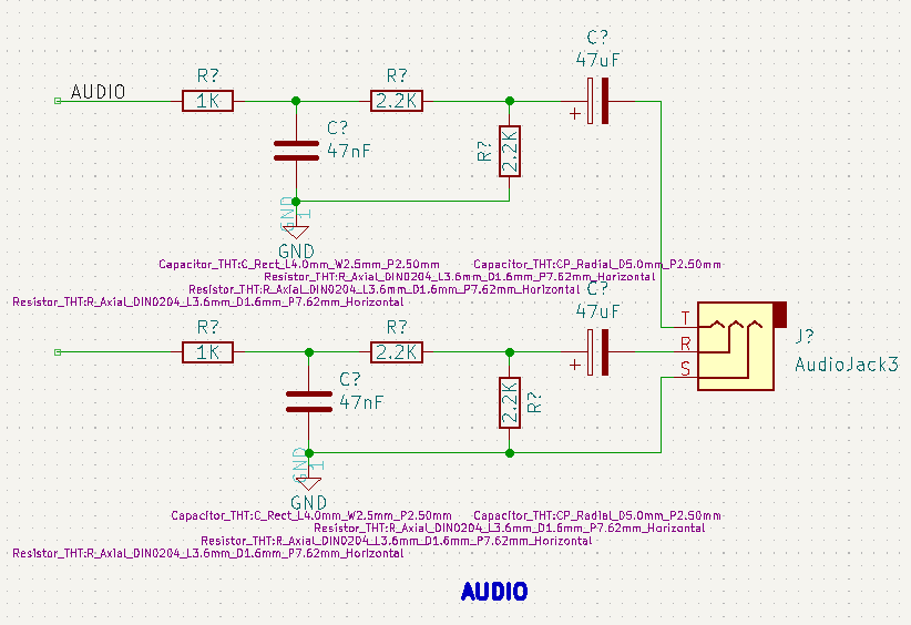
- Audio Filter Card
- JOYPAD Card
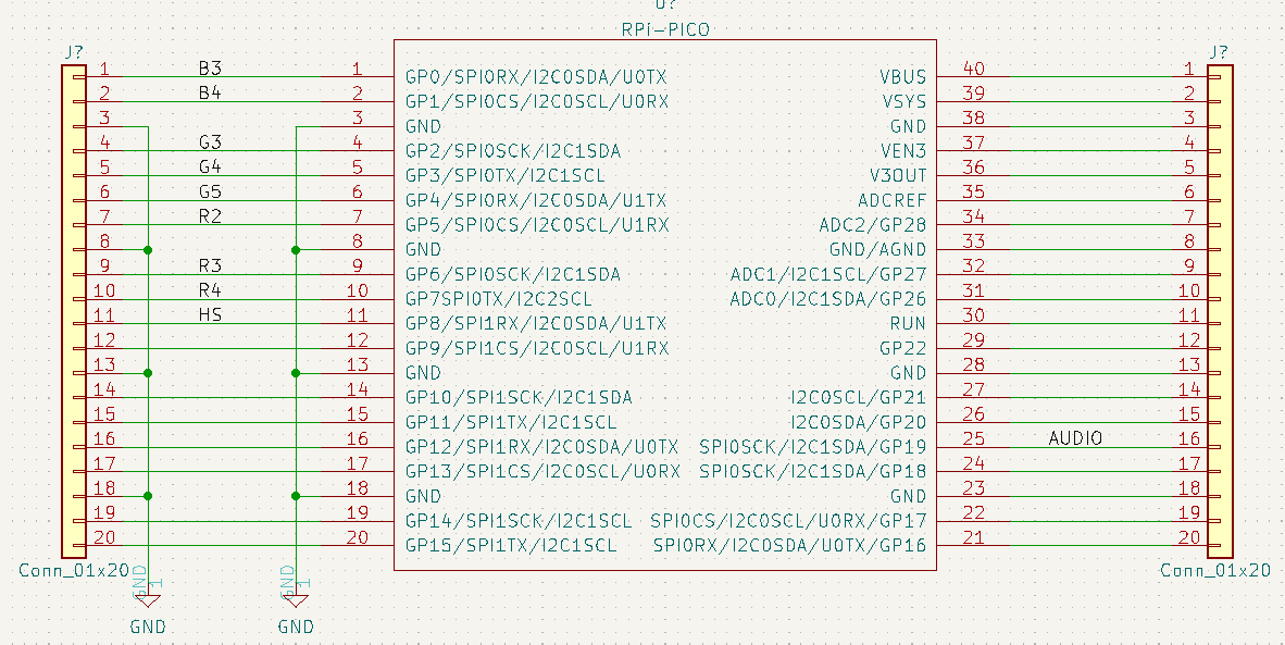
Raspberry Pi Pico Breakout Card
- Raspberry Pi Pico in Small Plastic Project Box - Breakout board
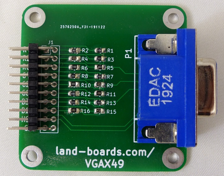
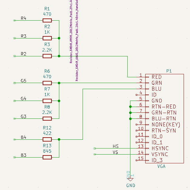
VGA Adapter Card
- VGAX49
- Built as VGAX49 3:3:2 8-bit build
Audio Filter Card
- GRID49-Audio Filter
- Repurposed from PiPicoMite01 Prototype build
Joy Stick (JoyPad)
Prototype Build Wiring
| Pico Pin | GPIO | Signal Name | Color | Dest | Pin |
|---|---|---|---|---|---|
| 1 | GP0 | B3 | BLU | VGAX49 | 13 |
| 2 | GP1 | B4 | BLU | VGAX49 | 12 |
| 3 | GND | GND | BRN | VGAX49 | 20 |
| 4 | GP2 | G3 | GRN | VGAX49 | 8 |
| 5 | GP3 | G4 | GRN | VGAX49 | 7 |
| 6 | GP4 | G5 | GRN | VGAX49 | 6 |
| 7 | GP5 | R2 | RED | VGAX49 | 3 |
| 9 | GP6 | R3 | RED | VGAX49 | 2 |
| 10 | GP7 | R4 | RED | VGAX49 | 1 |
| 11 | GP8 | CSYNC | GRY | VGAX49 | 17 |
| 21 | GP16 | BRN | JOYPAD | 10 | |
| 22 | GP17 | ORG | JOYPAD | 9 | |
| 23 | GND | GND | GRN | AUD-FILT | 2 |
| 24 | GP18 | YEL | JOYPAD | 8 | |
| 25 | GP19 | AUDIO | GRY | AUD-FILT | 1 or 3 |
| 26 | GP20 | GRN | JOYPAD | 7 | |
| 27 | GP21 | BLU | JOYPAD | 6 | |
| 28 | GND | GND | BLK | JOYPAD | 11 |
| 29 | GP22 | VIO | JOYPAD | 5 | |
| 31 | GP26 | GRY | JOYPAD | 4 | |
| 32 | GP27 | WHT | JOYPAD | 3 |
