ER-MOZZI-DB
Features
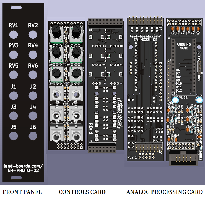
- Daughtercard to ER-PROTO-02 card
- Uses Front Panel and Controls card
- Controls card populated as required
- 0-6 Jacks, 0-6 Pots
- Controls card populated as required
- Uses Front Panel and Controls card
- Arduino NANO
- High Def Sound output
- Up to 6 Pots connected to A/D inputs
- Up to 4 input jacks connected to A/D inputs
- Options
- 0-4 Pots, 0-4 Input Jacks
- 5 Pots, 0-3 Input Jacks
- 6 Pots, 0-2 Input Jacks
Arduino Pins
- The ER-PROTO-02 controls card has 6 pots (RV1-RV6) and 6 jacks (J1-J6)
- One jack is a dedicated output (J6) connected to Hi Def output Arduino pins D9, D10
- The Arduino NANO has 8 Analog Inputs (0-7)
- RV1-RV3 go to Analog Inputs 0-2
- 3 Analog Inputs (Analog Inputs 3-5) get shared between 3 pots (RV4-RV6) and 3 jacks (J1-J3)
- If a jack is inserted, the jack is used and the pot is not connected
- If a jack is not inserted, the pot is used
- 2 Jacks (J4-J5) go to Analog Inputs 6-7
A0 - Analog Input 0
- RV1 wiper, 0-5V
- Install jumpers on controls card to pull up/down lines to pots
A1 - Analog Input 1
- RV2 wiper, 0-5V
- Install jumpers on controls card to pull up/down lines to pots
A2 - Analog Input 2
- RV3 wiper, 0-5V
- Install jumpers on controls card to pull up/down lines to pots
A3 - Analog Input 3
- J1 input Jack, 0-5V if jack is plugged into J1
- RV4 wiper if no jack is plugged into J1
A4 - Analog Input 4
- J2 input Jack, 0-5V if jack is plugged into J2
- RV5 wiper if no jack is plugged into J2
- Could be used for I2C SDA connection (no pot, no jack)
A5 - Analog Input 5
- J3 input Jack, 0-5V if jack is plugged into J3
- RV6 wiper if no jack is plugged into J3
- Could be used for I2C SCL connection (no pot, no jack)
A6 - Analog Input 6
- J4 Jack, 0-5V
- Could be either input or output
- Parts population option
A7 - Analog Input 7
- J5 Jack, 0-5V
- Could be either input or output
- Parts population option
J10 - Digital 6-13
- D9, D10 shared with <OZZI Digital
D9, D10 - High Def Audio Out
- J6 - Stereo 3.5mm jack (PJ-366ST)
- Same output on both stereo channel
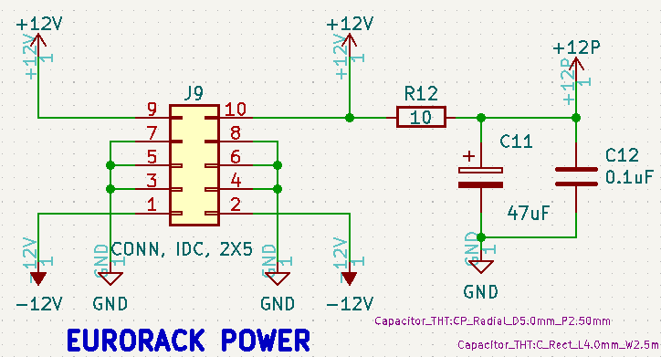
J9 - Eurorack Power
- Power filter
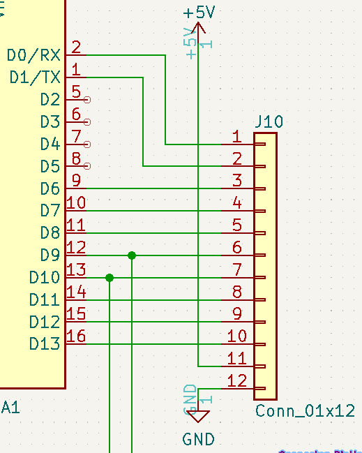
J10 - Digital I/O
- Pinout
- D0/RX
- D1/TX
- D6
- D7
- D8
- D9
- D10
- D11
- D12
- D13
- +5V
- GND
Software / Example Projects
- HAGIWO Bezier curve random CV generator
- HAGIWO Envelope Generator Module
- HAGIWO FM VCO Module
- HAGIWO Additive VCO (harmonic addition VCO)
- HAGIWO CHORD VCO with mozzi library
- Using Mozzi Library With 5 Potentiometers
- Atari Punk Synth V2
- Arduino Multi-pot Mozzi FM Synthesis
- Arduino mozzi FM VCO Module for 650 yen - Modular synth self-made
- Nuts and Volts AUDUINO Synth build for the Arduino NANO
- MozMo = ATMega328 plus FTDI
HAGIWO builds
Additive VCO
- HAGIWO Additive VCO Notes
- 3 pots (Fundamental Frequency, Inversion, Chord/Wave)
- 3 input jacks (V/Oct, CV Gain, CV Harmonic)
- 1 PWM output jack
- Additive VCO Code
Chord VCO
- HAGIWO Chord VCO
- 3 pots (Root Frequency, Harmonics Gain, Harmonics)
- 3 input jacks (V/Oct, CV Gain, CV Harmonic)
- 1 PWM output jack
- CHORD VCO Code
FM VCO
- HAGIWO FM VCO
- FM VCO Code
Issues
Rev 1
- Switch on jacks between RV and J not wired correctly
- Fixed in Rev 2 schematic
- Could cut pots and wire manually
- More easily just don't populate jack or pots that are not needed


