MMBASIC on XIAO RP2040
Contents
Overview
- Card set running BASIC Interpreter for the Raspberry Pi Pico on Seeed Studio XIAO RP2040
- MMBasic is a Microsoft BASIC compatible implementation of the BASIC language with floating point, integer and string variables, arrays, long variable names, a built in program editor and many other features
- 8 Flash locations for storage.
- Support for SD Card
MMBASIC Credits
Peter Mather led the project, ported the MMBasic interpreter to the Raspberry Pi Pico and wrote the hardware device drivers. Geoff Graham wrote the MMBasic interpreter and the manual. Mick Ames wrote the PIO compiler and its corresponding documentation.
Hardware
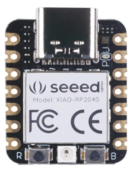
Seeed Studio XIAO RP2040
QT_Py_(RP2040_based) Wiki page
- Two manufacturers
- USB Type C connector
- RP2040 32-bit Cortex M0+ dual-core
- Runs at ~125 MHz
- 264 KB RAM
- SPI FLASH chip for storing files and CircuitPython/MicroPython code storage
- 8 MB - Adafruit
- 2 MB - Seeedstudio
- No EEPROM
- Can be used with C/C++ (Arduino), MicroPython, or CircuitPython
- Built-in RGB NeoPixel LED
- 13 GPIO pins (11 breakout pads and two QT pads):
- Four 12 bit ADCs (one more than Pico)
- I2C port
- 2 I2C: 1 on QT pins, one on the (Adafruit) breakout pads - Adafruit
- 1 I2C on XAIO
- SPI and UART peripherals, in standard QT Py locations,
- PWM outputs on every IO pin - for servos, LEDs, etc
- There are 6 GPIO in consecutive order for PIO compatibility
- 3.3V logic and power 600 mA
- Both Reset button and Bootloader select buttons for quick restarts (no unplugging-replugging to relaunch code)
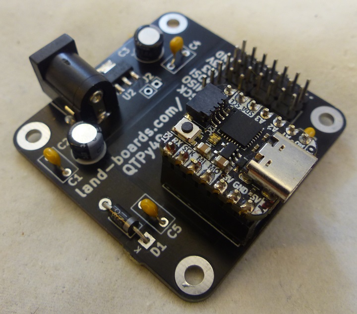
QTPy49 breakout card
QTPy49 Wiki page
- CPU choices are
- QT Py (SAMD based)
- QT Py (RP2040 based)
- XIAO ESP32C3
- SeeedStudio XIAO ESP32C3 (New 2022-07)
- RISC-V Single Core
- Up to 160 MHz
- 400 KB SRAM
- 4 MB Flash
- 2.4GHz Wi-Fi subsystem
- Wiki
- ESP32C3 Datasheet
- Connectors/Headers
- DC Power
- AD0 GVS
- AD1 GVS
- AD2 GVS
- AD3 GVS
- I2C with ground/VCC
- TX/RX with ground/VCC
- SPI with ground/VCC
- QTPy49 can be powered from with either the USB C or DC jack
- Automatic Schottky diode power switching between
- 5V from USB C
- 5V on external DC jack
- 7-12V on DC jack
- Automatic Schottky diode power switching between
- 49x49mm ODAS form factor
- (4) 4-40 mounting holes
SD Card
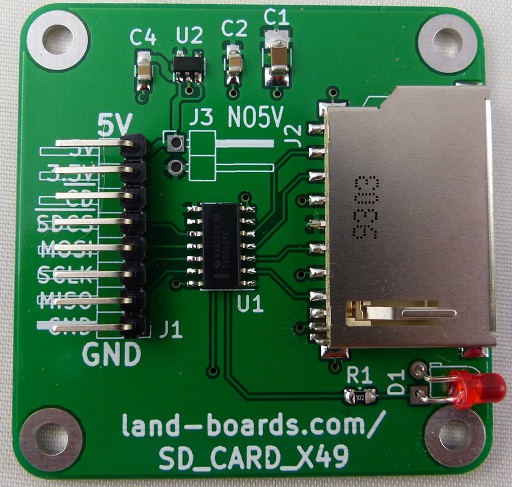
SD_CARD_X49 wiki page
- SD or SDHC card adapter
- 5V to 3.3V regulator
- 3.3V to 5V TXS0104E level shifter
- Activity LED
- 49 x 49 mm ODAS foprm factor
- (4) 4-40 mounting holes
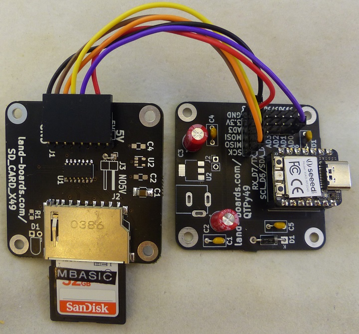
SD Card Wiring
- SD_CARD_X49 card
- NO5V jumper installed
| Signal | SD_CARD_X49 | QTPy49 conn | QTPy GP | PiPico Pin |
|---|---|---|---|---|
| SPI_SCLK | J1-3 | J3-6 | GP2 | GPIO2 |
| SPI_MOSI | J1-4 | J3-4 | GP3 | GPIO3 |
| SPI_MISO | J1-2 | J3-5 | GP4 | GPIO4 |
| SPI_SS | J1-5 | J9-3 | GP26 | GPIO26 |
| GND | J1-1 | J9-1 | GND | GND |
| VCC (3.3V) | J1-7 | J9-2 | VCC | VCC |
SD Configuration
OPTION SYSTEM SPI GP2, GP3, GP4
OPTION SDCARD GP26
OPTION COLOURCODE ON
- Verify it is working
> FILES
A:/
   <DIR>  basic
   <DIR>  bmps
   <DIR>  demos
   <DIR>  games
   <DIR>  jpegs
   <DIR>  lbcards
   <DIR>  performance
   <DIR>  wave
8 directories, 0 files
RS-232 (option)
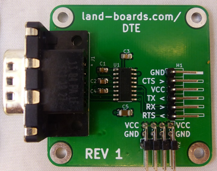
DTE wiki page
- TTL to RS-232 converter
- Male DB-9 connector
- FTDI pinout (reversed directions to directly connect to FTDI Interface)
- 49x49mm card
- 4x 4-40 holes
- DTE card
- Command to use serial as console
OPTION SERIAL CONSOLE GP0, GP1
- Command to use serial as COM port
- 115,200 baud
setpin gp1,gp0, com1
open "com1:9600" as #5
print #5, :Hello"
RS-232 Wiring
- Wiring to DTE card
| DTE signal | DTE pin | QTPy GP | PiPico Pin |
|---|---|---|---|
| GND | H1-1 | GND | J4-1 |
| CTS | H1-2 | N/C | N/C |
| VCC | H1-3 | VCC | J4-2 |
| TX | H1-4 | TX_D6 | J4-3 |
| RX | H1-5 | RX_D7 | J4-4 |
| RTS | H1-6 | N/C | N/C |
- Wiring to FTDI-49MM card
- Swap TX/RX pins
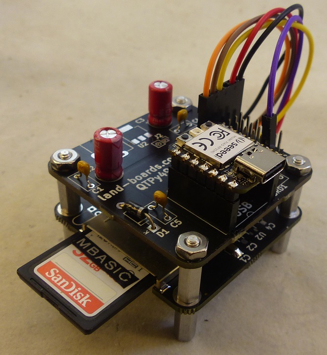
MMBASIC Card Stack-up
Software
Install MMBASIC on Seeed XIAO RP2040
- Hold down the "BOOT" button
- The "B" is written on the board shown to the right
- Connect the XIAO RP2040 via USB C cable to your computer while still pressing the button
- The computer then will appear a disk driver(RP1-RP2)
- Download the PicoMite_Firmware.zip
- Drag the .uf2 file to the disk drive ("RP1-RP2")
- Card will re-boot
- Connect in TeraTerm over serial
- Free memory
> print mm.ver
 5.070501

> memory

Program:
   0K ( 0%) Program (0 lines)
 124K (100%) Free

RAM:
   1K ( 1%) 3 Variables
   0K ( 0%) General
 155K (99%) Free
GPIO from MMBASIC
| QTPy49 Marking | GPIO |
|---|---|
| A0 | GP26 (SD_SS) |
| A1 | GP27 |
| A2 | GP28 |
| A3 | GP29 |
| I2C_SDA | GP6 |
| I2C_SCL | GP7 |
| RX | GP1 |
| TX | GP0 |
MMBASIC - Using Pins
- Digital I/O
SETPIN GP27, DIN:' Digital Input
SETPIN GP28, DOUT:' Digital Output
PIN(GP28) = 1:'Digital output
- Analog Input
SETPIN GP29, AIN:' Analog Input
- SETPIN(s) for Serial and I2C
SETPIN GP1, GP0, COM1
SETPIN GP6, GP7 I2C2
On-Board LED
- No Built-in support in MMBASIC for the on-board NEOPIXEL
- Red, Green, Blue LED
- Pull Low to turn on RGB LED bits
- At-boot - RGB LED blinks Cyan/Green by MMBASIC
- Red LED = GP17
- Green LED = GP16
- Blue LED = GP25 (Used by MMBASIC)
' Make pins outputs
SETPIN GP17, DOUT:' Red LED
SETPIN GP16, DOUT:' Green LED
SETPIN GP25, DOUT:' Blue LED
' Turn off LEDS
PIN(GP17)=1:' Turn off Red LED
PIN(GP25)=1:' Turn off Blue LED
PIN(GP16)=1:' Turn off Green LED
' Turn on LEDs
PIN(GP17)=0:' Turn on Red LED
PIN(GP25)=0:' Turn on Blue LED
PIN(GP16)=0:' Turn on Green LED
Demo Code
- SD Card contents
- PROTO16_LEDs.bas
- Bounces a bit across the PROTO16-I2C card
- PROTO16_LEDs.bas
