BrBdPwrSply
Contents
Background
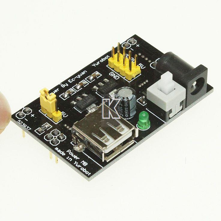
I bought one of those cheap MB102 breadboard power supplies from China and although at $3 (incl shipping) the price was right, the features just weren't quite right.
They do some things almost too clever. They have both 5V and 3.3V power supplies on the board, but they don't allow one of the rails to be +5V and the other rail to be 3.3V at the same time. Sure, it can be bypassed by jumpers, but why?
Simpler Design Approach
I wanted a breadboard power supply which is "simpler". I tend to work with mixed 5V and 3.3V stuff often enough that it would be worthwhile to have one of the rails at 5V and the other at 3.3V.
I don't find the power switch necessary although it's pretty cool, I guess but I can just pull out the cable when I am done using the card.
Also, at first I liked the USB jack for power, but I'm fairly sure I'd rather just use a wall wart and not tie up one of my USB ports. Plus, I'd rather have more current than the 1/2 Amp that the USB puts out. Not only that but I don't want to risk damage to my expensive computer.
I figured that I could make a card that is significantly smaller as well.
I don't think I could ever make a card that is as cheap, but in theory, this card is smaller and has less parts so if it was produced in China in volume it would be cheaper.
The Design
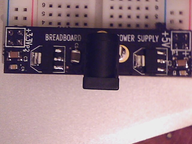
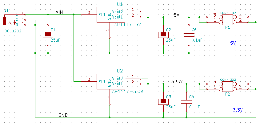
My design has a 2.1mm power jack for input power.
I used two regulators, one for +5V and the other for +3.3V. I made the board area under the regulators as big as I could for heat sinking. I chose the same regulator parts that the Arduino uses - the AP1117.
The board height is slightly over two inches (the side that spans the rails). The part that overlaps the board will only need three rows of pins (2 for connection and one for board edge overlap).
Bbps 005.png Bbps 006.png
Strange Dimensions
An odd thing about the dimensions of the 830 point breadboards is that the outer pins are not on 0.1" spacing compared to the breadboard pins. I measured 1.895 from the outside of the pins on the board that I have using my Harbor Freight calipers. The pins are 0.025" wide so that would mean that the center of the outside pins is 1.895 - 0.025 = 1.870". That might be right, but my guess is it should be more like 1.875" so that's what I layed out on my board.
Parts List
Descr	Qty	Footprint	Ref Des	Manuf	Manuf PN	Vendor<//td>	Vendor PN
0.1uF	2	SM0805	C4, C5	AVX	08055C104KAT2A	MOUSER	581-08055C104K
22uF	3	SM1210	C1, C2, C3	TDK	C3225Y5V1A226Z	MOUSER	810-C3225Y5V1A226Z
AP1117-3.3V	1	SOT223	U2	Diodes	AP1117E33G-13	Mouser	621-AP1117E33G-13
AP1117-5V	1	SOT223	U1	Diodes Inc	AP1117E50G-13	Mouser	621-AP1117E50G-13
CONN_2X2	2	PIN_ARRAY_2X2	P1, P2	FCI	78548-406HLF	MOUSER	649-78548-406HLF
DCJ0202	1	JACK_2.1MM	J1	Kobiconn	163-179PH-EX	Mouser	163-179PH-EX
Rev X3 Updates
- Silkscreen changes
- Moved headers to rear side
- Added marking to headers to separate power and ground sides
- Added + and - markings
- Changed C2, C3 to 10 uF
- Changed C1 footprint to SM1812


