Difference between revisions of "DIGIO-128"
Jump to navigation
Jump to search
Blwikiadmin (talk | contribs) |
Blwikiadmin (talk | contribs) |
||
| Line 37: | Line 37: | ||
[[File:DIGIO-128-I2C-Addrs-X2.PNG]] | [[File:DIGIO-128-I2C-Addrs-X2.PNG]] | ||
| − | |||
| − | |||
| − | |||
| − | |||
| − | |||
| − | |||
| − | |||
| − | |||
== Connectors == | == Connectors == | ||
| Line 90: | Line 82: | ||
* [[Arduino Based Test Station]] | * [[Arduino Based Test Station]] | ||
* [https://github.com/land-boards/lb-Arduino-Code/tree/master/LBCards/ODAS/ODASTESTER ODAS Tester Github Repo] | * [https://github.com/land-boards/lb-Arduino-Code/tree/master/LBCards/ODAS/ODASTESTER ODAS Tester Github Repo] | ||
| + | |||
| + | == Software Examples/Drivers == | ||
| + | |||
| + | * [https://github.com/land-boards/lb-Arduino-Code/tree/master/LBCards/DIGIO128 DIGIO-128 Arduino example code] | ||
| + | * [https://github.com/land-boards/lb-Arduino-Code/tree/master/libraries/LandBoards_Digio128V2 DIGIO-128 Arduino Driver] | ||
| + | * [https://github.com/land-boards/lb-Arduino-Code/tree/master/libraries/LandBoards_Digio128_64 DIGIO-128 - 64-bit version Arduino Driver] | ||
| + | * [https://github.com/land-boards/lb-Python-Code/tree/master/MicroPython/ESP32/libraries/digio128 DIGIO-128 Micropython Driver (ESP-32)] | ||
| + | * [https://github.com/land-boards/RasPi/blob/master/ODAS/DIGIO128/RasPiDigio128.py Raspberry Pi Example Code] - Requires some knowledge of the [http://ww1.microchip.com/downloads/en/DeviceDoc/20001952C.pdf MCP23017 (datasheet)] | ||
== Assembly Sheet == | == Assembly Sheet == | ||
Revision as of 19:02, 15 March 2022
Contents
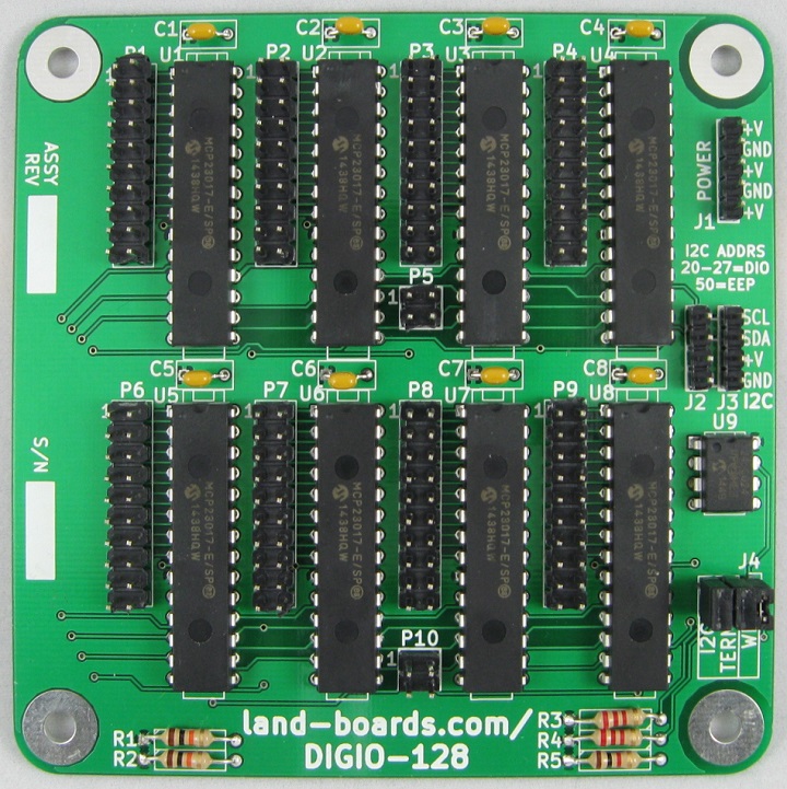
DIGIO-128 Card
Features
- (8) of MCP23017 - 16 bit GPIO x 8
- Total of 128 bits of GPIO
- I2C host interface
- MCP23017] I2C Parallel I/O
- Two Wire interface
- 100/400 KHZ operation
- 25mA sink/source capability per I/O
- Jumper selectable terminators
- Single 4-pin host interface connector (Ground, Power, Clock, Data)
- 0.1" Pitch I/O Connectors
- 16 digital I/O
- 2 Power
- 2 Ground
- Interrupt connectors
- I2C Connector
- Power Connector
- 24LC024 I2C Personality EEPROM
- 3.3V or 5V operation
- Compatible with Arduino, Raspberry Pi, BeagleBone Black
- 95x95mm form factor
- (4) 6-32 mounting holes - one on each corner
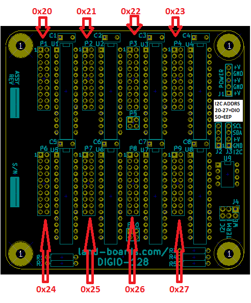
I2C Addresses
- MCP23017 parts 0x20 - 0x27
- EEPROM 24LC024 = 0x50
Connectors
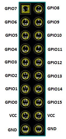
P1-P4, P6-P9 - Digital I/O Connector
- 16 bits per connector
- (2) Power
- (2) Ground
P5, P10 - Interrupt Outputs
- Useful for detecting input changes or levels
- Can be ignored if not needed
- If the inputs are polled, the pins can be ignored
J1 - External Power
- Can be ignored if the card is powered through I2C connector
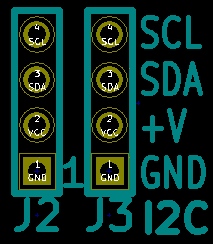
J2, J3 - I2C Connectors
- Daisy chained connections
- 2nd connector can be ignored
- Card can be powered through this connector(s)
J4 - I2C Terminators and EEPROM Write Enable
- SDA, SCL I2C Terminators
- Install jumper to use terminators
- WE - EEPROM Write Enable
- Install To enable writing config EEPROM
Schematics
Testing
Software Examples/Drivers
- DIGIO-128 Arduino example code
- DIGIO-128 Arduino Driver
- DIGIO-128 - 64-bit version Arduino Driver
- DIGIO-128 Micropython Driver (ESP-32)
- Raspberry Pi Example Code - Requires some knowledge of the MCP23017 (datasheet)


