ER-PROTO-02 Rev 1 Assembly Sheet
Jump to navigation
Jump to search
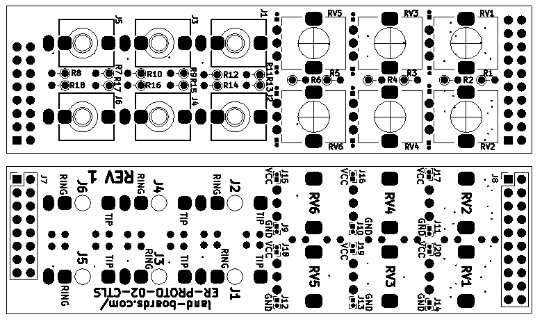
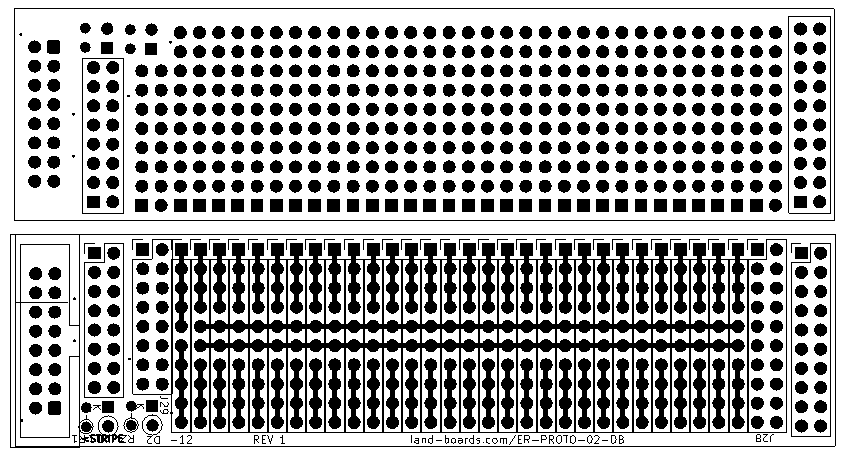
- Three card set
- Front panel
- Controls card
- Prototyping Daughtercard
Controls Card
- J1-J6 PJ366ST (stereo) or PJ368SM (Top, tip switch)
- RV1-RV6 = pots
- R1-R6 are series resistors for pots RV1-RV6
- R7, R9, R11, R13, R15, R17: Tip resistors
- R8, R10, R12, R14, R16, R18: Ring/Switch resistors
- J7 = 2X8 Female Header
- J8 = 2x10 Female Header
Prototyping Daughtercard
- J8 = 2x10 male header
- J7 = 2x8 male header
- J9 = 2x5 or 2x8 IDC box header
- 2x5 if no +5V is used
- 2x8 if +5V is used
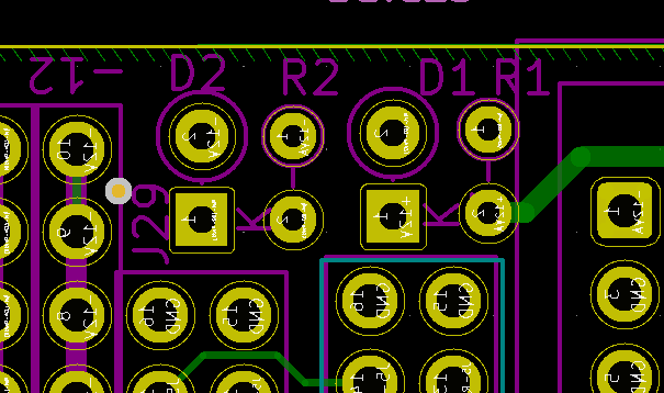
- R1, R2: 10 Ohms
- D1, D2: Schottky Diodes
- R1, R2, C1, C2


