Frequency Counter
Jump to navigation
Jump to search
Contents
Features
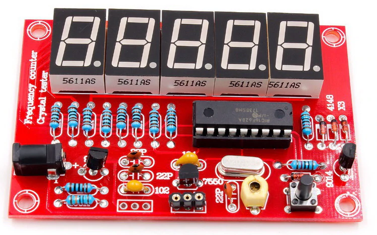
- Original Design by DL4YHF
- Frequency range: 1 Hz-50 MHz
- Crystal Test Range: 4 MHz-48 MHz
- Mods to replace crystal checker with sensitive pre-amp
- PIC-freq.counter-modification
- PCB size:8*5.3cm
- Fits in 100 x 60 x 25 mm enclosure
- Source - AliExpress Frequency Counter - Very inexpensive
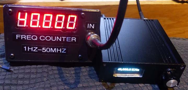
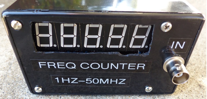
Built into case
- P-Touch white on black labels
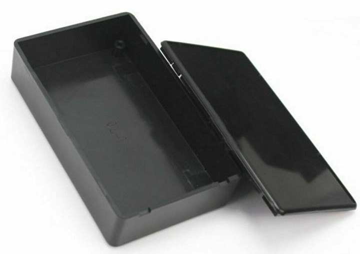
- 100x60x25mm Black Plastic Electronic Project Box Enclosure Instrument Case - Inexpensive plastic case
- Plastic Waterproof Cover Electronic Project Instrument Enclosure DIY Box Case Junction Box Housing 100 x 60 x 25 mm Black
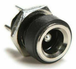
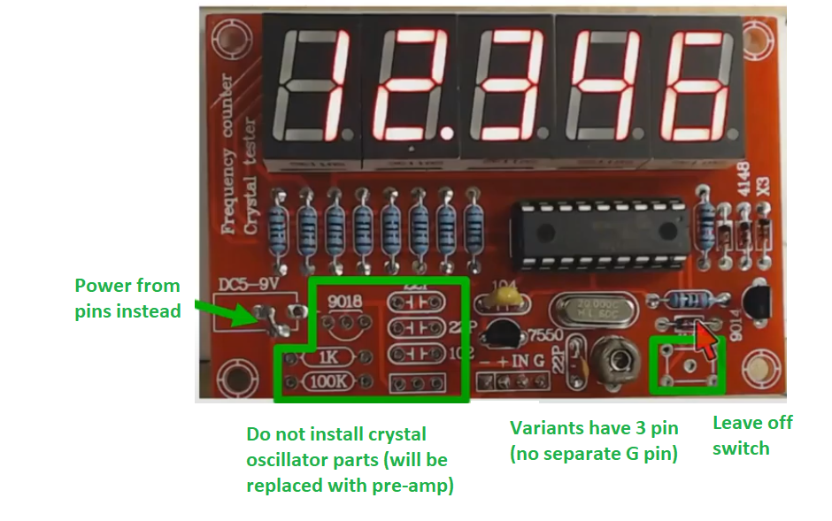
- 7-9V in
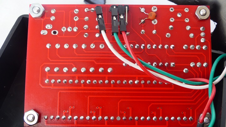
- Right angle header pins pointing to inside of card
- 4-40 x 3/16” Machine Screws
- 4-40 Standoffs
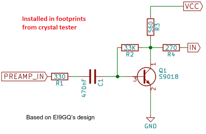
Rework - Add Pre-Amp
- Re-uses extra HF transistor that would have been used by crystal tester oscillator
- AC coupled input
- Based on
Pre-Amp schematic
When building kit, do not install
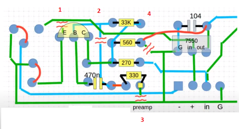
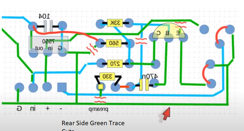
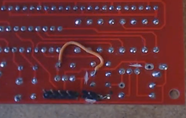
Cuts/Jumpers
- Four cuts
- Blue = 1 front side cut
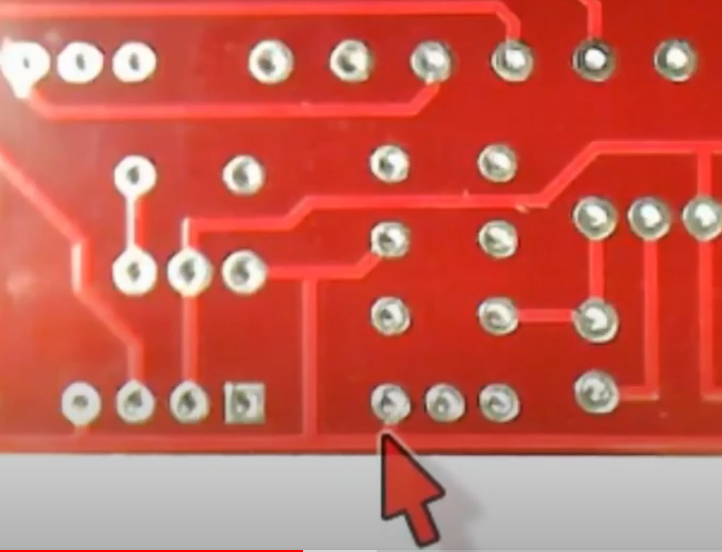
- Green = 3 back side cuts
- Jumpers Red
- Green = Back side cuts
- Short etch on one cut
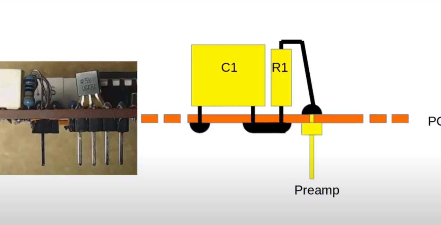
- Details of preamp input pin
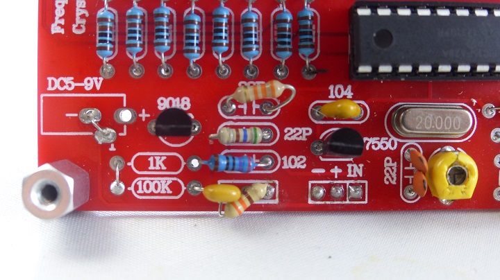
- With parts
- Wire on back
Initial Testing
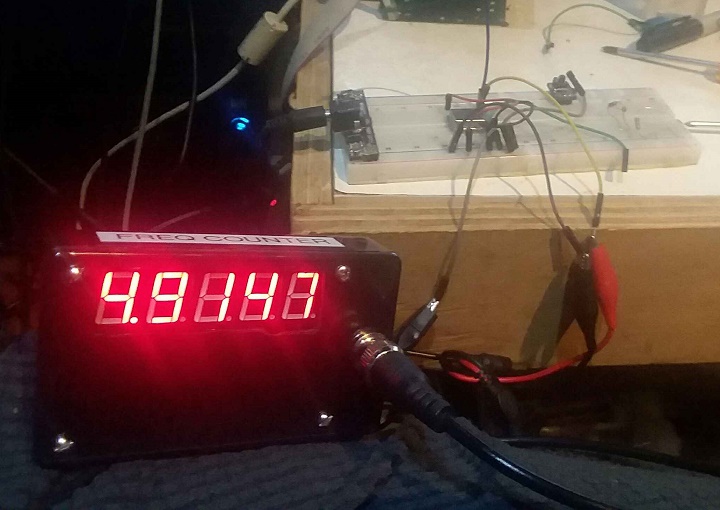
- 4.9152 MHz crystal oscillator
- Scope frequency counter shows 4.19520 MHz
- Freq Counter displays 4.9747 MHz
- Difference = 500 Hz or 0.1% accuracy
- Can only adjust the variable capacitor in narrow range
- Freq = 25,000 MHz - measured = 24.997 MHz
- Error = 3 KHz / 25,000 KHz = 0.012%
- Freq = 10.000 Hz - measured = 9.999 Hz = .01% error
Fixing the frequency error
- Calibrated using VFO-001 calibrated to WWV
- Replaced 22 pF cap with 2 series 33 pF caps
- Far right near variable cap
- Added 22 pF to back of board
- Upper mid right
- Why was this an error?
- Perhaps the variable cap is too small for proper loading of the crystal
- Could possible parallel a 10 pF cap with the variable cap?
Firmware Mods
Reviews / Builds
