Difference between revisions of "Frequency Counter"
Jump to navigation
Jump to search
Blwikiadmin (talk | contribs) (→Case) |
Blwikiadmin (talk | contribs) (→Case) |
||
| Line 25: | Line 25: | ||
* [https://www.aliexpress.com/item/32833340145.html?spm=a2g0o.productlist.0.0.68406390LYz5Rw&algo_pvid=0bbf736e-a88e-4ac7-9adc-03df1259669a&algo_expid=0bbf736e-a88e-4ac7-9adc-03df1259669a-0&btsid=0bb0622a16017274930362968ef528&ws_ab_test=searchweb0_0,searchweb201602_,searchweb201603_ BNC connector - female chassis mount] | * [https://www.aliexpress.com/item/32833340145.html?spm=a2g0o.productlist.0.0.68406390LYz5Rw&algo_pvid=0bbf736e-a88e-4ac7-9adc-03df1259669a&algo_expid=0bbf736e-a88e-4ac7-9adc-03df1259669a-0&btsid=0bb0622a16017274930362968ef528&ws_ab_test=searchweb0_0,searchweb201602_,searchweb201603_ BNC connector - female chassis mount] | ||
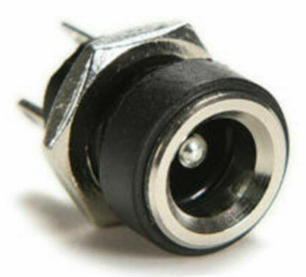
* [https://www.ebay.com/itm/USA-12-PCS-5-5-MMX-2-1-MM-CHASSIS-PANEL-MOUNT-FEMALE-POWER-JACK-SOCKETS-NEW/264838025913?ssPageName=STRK%3AMEBIDX%3AIT&_trksid=p2057872.m2749.l2649 5.1mm Chassis mount power connector] | * [https://www.ebay.com/itm/USA-12-PCS-5-5-MMX-2-1-MM-CHASSIS-PANEL-MOUNT-FEMALE-POWER-JACK-SOCKETS-NEW/264838025913?ssPageName=STRK%3AMEBIDX%3AIT&_trksid=p2057872.m2749.l2649 5.1mm Chassis mount power connector] | ||
| − | + | ||
| + | [[File:Power_5-1mm.PNG]] | ||
| + | |||
| + | * 7-9V in | ||
* Right angle header pins pointing to inside of card | * Right angle header pins pointing to inside of card | ||
* 4-40 x 3/16” Machine Screws | * 4-40 x 3/16” Machine Screws | ||
Revision as of 14:24, 3 October 2020
Contents
Features
- Original Design by DL4YHF
- Frequency range: 1 Hz-50 MHz
- Crystal Test Range: 4 MHz-48 MHz - Replaced with pre-amp circuit
- PCB size:8*5.3cm
- Fits in 100 x 60 x 25 mm enclosure
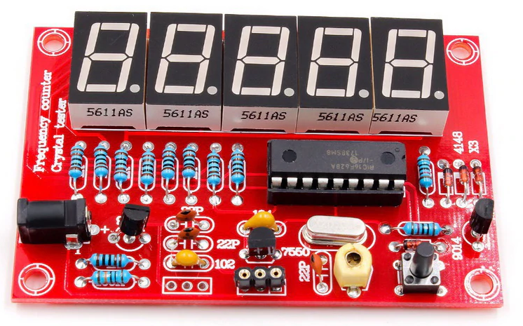
- Source - AliExpress Frequency Counter - Very inexpensive
- PIC-freq.counter-modification
Case
- P-Touch white on black labels
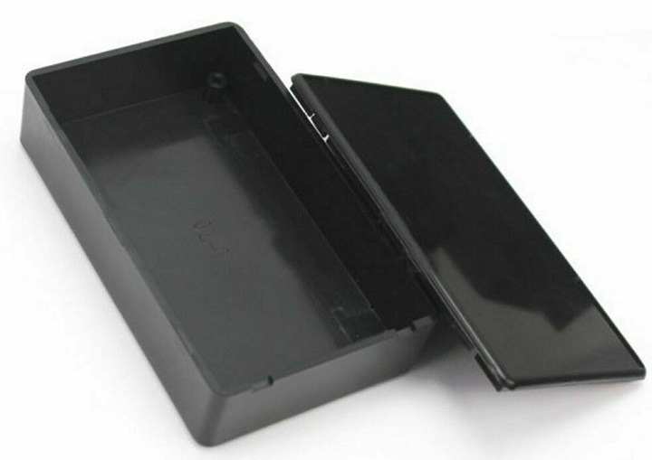
- 100x60x25mm Black Plastic Electronic Project Box Enclosure Instrument Case - Inexpensive plastic case
- Plastic Waterproof Cover Electronic Project Instrument Enclosure DIY Box Case Junction Box Housing 100 x 60 x 25 mm Black
- 7-9V in
- Right angle header pins pointing to inside of card
- 4-40 x 3/16” Machine Screws
- 4-40 Standoffs
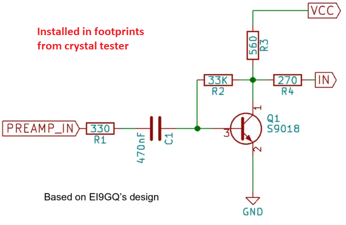
Rework - Add Pre-Amp
- Re-uses extra HF transistor that would have been used by crystal tester oscillator
- AC coupled input
- Based on
Pre-Amp schematic
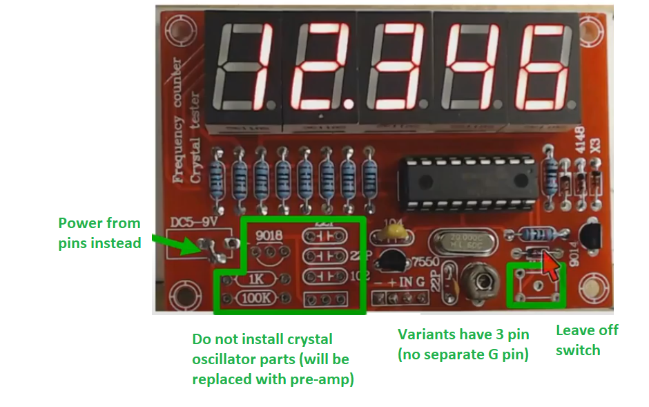
When building kit, do not install
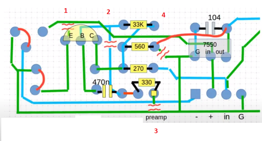
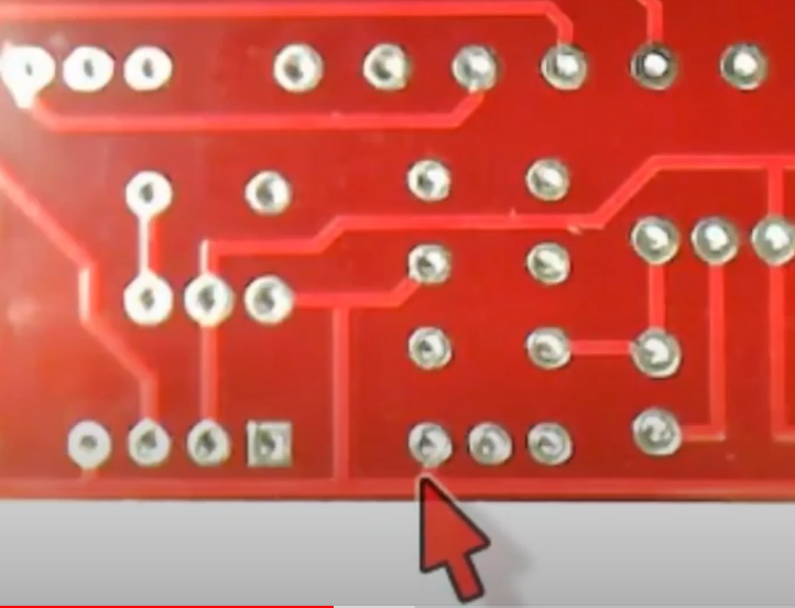
Cuts/Jumpers
- Four cuts
- Blue = 1 front side cut
- Green = 3 back side cuts
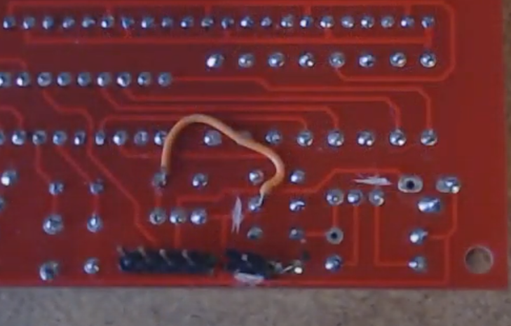
- Jumpers Red
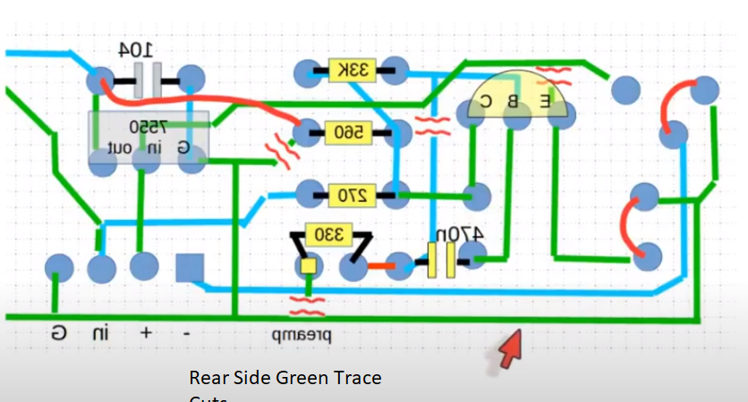
- Green = Back side cuts
- Short etch on one cut
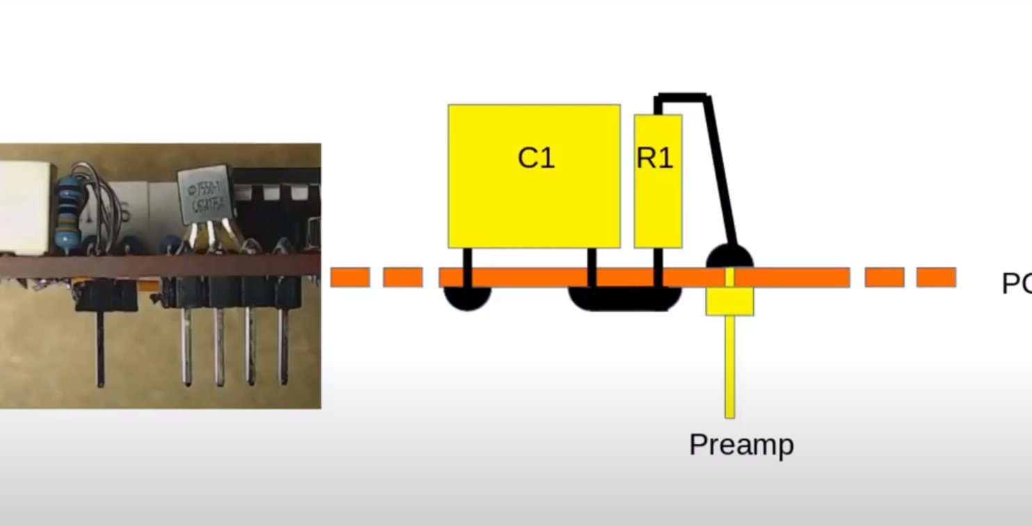
- Details of preamp input pin
- With parts
- Wire on back
Testing
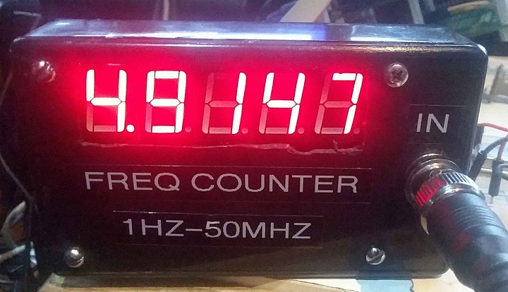
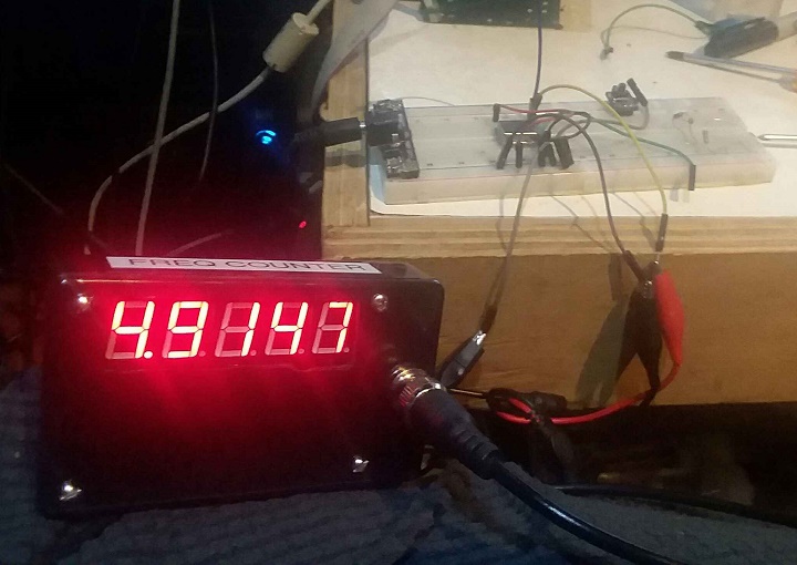
- 4.9152 MHz crystal
- Scope frequency counter shows 4.19520 MHz
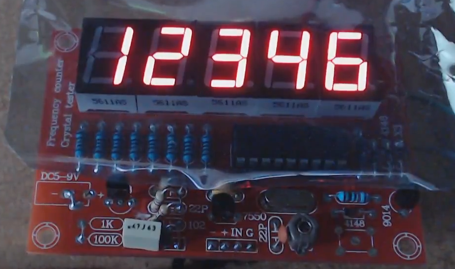
- Freq Counter displays 4.9747 MHz
- Difference = 500 Hz or 0.1% accuracy
- Can only adjust the variable capacitor in narrow range
Reviews / Builds
